ZHCSCK8H May 2014 – April 2025 LP8860-Q1
PRODUCTION DATA
- 1
- 1 特性
- 2 應用
- 3 說明
- Device Comparison Table
- 4 Pin Configuration and Functions
-
5 Specifications
- 5.1 Absolute Maximum Ratings
- 5.2 ESD Ratings
- 5.3 Recommended Operating Conditions
- 5.4 Thermal Information
- 5.5 Electrical Characteristics
- 5.6 Current Sinks Electrical Characteristics
- 5.7 Boost Converter Characteristics
- 5.8 Logic Interface Characteristics
- 5.9 VIN Undervoltage Protection (VIN_UVLO)
- 5.10 VDD Undervoltage Protection (VDD_UVLO)
- 5.11 VIN Overvoltage Protection (VIN_OVP)
- 5.12 VIN Overcurrent Protection (VIN_OCP)
- 5.13 Power-Line FET Control Electrical Characteristics
- 5.14 External Temp Sensor Control Electrical Characteristics
- 5.15 I2C Serial Bus Timing Parameters (SDA, SCLK)
- 5.16 SPI Timing Requirements
- 5.17 Typical Characteristics
-
6 Detailed Description
- 6.1 Overview
- 6.2 Functional Block Diagram
- 6.3 Feature Description
- 6.4 Device Functional Modes
- 6.5 Programming
- 6.6
Register Maps
- 6.6.1
Register Bit Explanations
- 6.6.1.1 Display/Cluster1 Brightness Control MSB
- 6.6.1.2 Display/Cluster1 Brightness Control LSB
- 6.6.1.3 Display/Cluster1 Output Current MSB
- 6.6.1.4 Display/Cluster1 Output Current LSB
- 6.6.1.5 Cluster2 Brightness Control MSB
- 6.6.1.6 Cluster2 Brightness Control LSB
- 6.6.1.7 Cluster2 Output Current
- 6.6.1.8 Cluster3 Brightness Control MSB
- 6.6.1.9 Cluster3 Brightness Control LSB
- 6.6.1.10 Cluster3 Output Current
- 6.6.1.11 Cluster4 Brightness Control MSB
- 6.6.1.12 Cluster4 Brightness Control LSB
- 6.6.1.13 Cluster4 Output Current
- 6.6.1.14 Configuration
- 6.6.1.15 Status
- 6.6.1.16 Fault
- 6.6.1.17 LED Fault
- 6.6.1.18 Fault Clear
- 6.6.1.19 Identification
- 6.6.1.20 Temp MSB
- 6.6.1.21 Temp LSB
- 6.6.1.22 Display LED Current MSB
- 6.6.1.23 Display LED Current LSB
- 6.6.1.24 Display LED PWM MSB
- 6.6.1.25 Display LED PWM LSB
- 6.6.1.26 EEPROM Control
- 6.6.1.27 EEPROM Unlock Code
- 6.6.2
EEPROM Bit Explanations
- 6.6.2.1 EEPROM Register 0
- 6.6.2.2 EEPROM Register 1
- 6.6.2.3 EEPROM Register 2
- 6.6.2.4 EEPROM Register 3
- 6.6.2.5 EEPROM Register 4
- 6.6.2.6 EEPROM Register 5
- 6.6.2.7 EEPROM Register 6
- 6.6.2.8 EEPROM Register 7
- 6.6.2.9 EEPROM Register 8
- 6.6.2.10 EEPROM Register 9
- 6.6.2.11 EEPROM Register 10
- 6.6.2.12 EEPROM Register 11
- 6.6.2.13 EEPROM Register 12
- 6.6.2.14 EEPROM Register 13
- 6.6.2.15 EEPROM Register 14
- 6.6.2.16 EEPROM Register 15
- 6.6.2.17 EEPROM Register 16
- 6.6.2.18 EEPROM Register 17
- 6.6.2.19 EEPROM Register 18
- 6.6.2.20 EEPROM Register 19
- 6.6.2.21 EEPROM Register 20
- 6.6.2.22 EEPROM Register 21
- 6.6.2.23 EEPROM Register 22
- 6.6.2.24 EEPROM Register 23
- 6.6.2.25 EEPROM Register 24
- 6.6.1
Register Bit Explanations
-
7 Application and Implementation
- 7.1 Application Information
- 7.2
Typical Applications
- 7.2.1
Typical Application for Display Backlight
- 7.2.1.1 Design Requirements
- 7.2.1.2
Detailed Design Procedure
- 7.2.1.2.1 Inductor Selection
- 7.2.1.2.2 Output Capacitor Selection
- 7.2.1.2.3 Input Capacitor Selection
- 7.2.1.2.4 Charge Pump Output Capacitor
- 7.2.1.2.5 Charge Pump Flying Capacitor
- 7.2.1.2.6 Diode
- 7.2.1.2.7 Boost Converter Transistor
- 7.2.1.2.8 Boost Sense Resistor
- 7.2.1.2.9 Power Line Transistor
- 7.2.1.2.10 Input Current Sense Resistor
- 7.2.1.2.11 Filter Component Values
- 7.2.1.3 Application Performance Plots
- 7.2.2 Low VDD Voltage and Combined Output Mode Application
- 7.2.3 High Output Voltage Application
- 7.2.4 High Output Current Application
- 7.2.5 Three-Channel Configuration Without Serial Interface
- 7.2.6 Solution With Minimum External Components
- 7.2.1
Typical Application for Display Backlight
- 7.3 Power Supply Recommendations
- 7.4 Layout
- 8 Device and Documentation Support
- 9 Revision History
- 10Mechanical, Packaging, and Orderable Information
7.2.1.2.11.1 Critical Components for Design
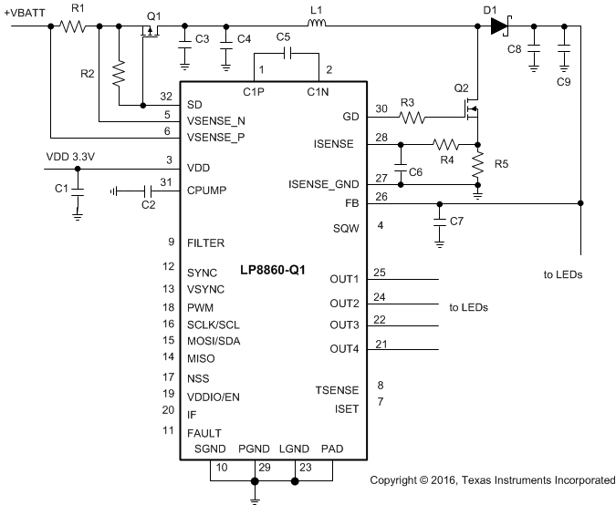
Schematic on Figure 7-3 shows the critical part of circuitry: boost components, the LP8860-Q1 internal charge pump for gate driver powering and powering/grounding of LP8860-Q1 boost components. Layout example for this is shown in Figure 7-15.
 Figure 7-3 Critical Components for Design
Table 7-3 Bill of Materials for Design Example
| REFERENCE DESIGNATOR | DESCRIPTION | NOTE |
|---|---|---|
| R1 | 20 m? 3 W | Input current sensing resistor |
| R2 | 20 k? 0.1 W | Power-line FET gate pullup resistor |
| R3 | 10 ? 0.1 W | Gate resistor for boost FET |
| R4 | 10 ? 0.1 W | Current sensing filter resistor |
| R5 | 25 m? 3 W | Boost current sensing resistor |
| C1 | 1 μF 10 V ceramic capacitor | VDD bypass capacitor |
| C2 | 10 μF 16 V ceramic capacitor | Charge pump output capacitor |
| C3 | 33 μF 50 V electrolytic capacitor | Boost input capacitor |
| C4 | 10 μF 50 V ceramic capacitor | Boost input capacitor |
| C5 | 1 μF 10 V ceramic capacitor | Flying capacitor |
| C6 | 1000 pF 10 V ceramic capacitor | Current sensing filter capacitor |
| C7 | 39 pF 50 V ceramic capacitor | High frequency bypass capacitor |
| C8 | 33 μF 50 V electrolytic capacitor | Boost output capacitor |
| C9 | 10 μF 100 V ceramic capacitor | Boost output capacitor |
| L1 | 22 μH saturation current 9 A | Boost inductor |
| D1 | 60 V 15 A Schottky diode | Boost Schottky diode |
| Q1 | 60 V 10 A pMOSFET | Power-line FET |
| Q2 | 60 V 15 A nMOSFET | Boost nMOSFET |