ZHCSHW2I June 2007 – September 2018 LM2735
PRODUCTION DATA.
- 1 特性
- 2 應用
- 3 說明
- 4 修訂歷史記錄
- 5 Pin Configuration and Functions
- 6 Specifications
- 7 Detailed Description
-
8 Application and Implementation
- 8.1 Application Information
- 8.2
Typical Applications
- 8.2.1 LM2735X SOT-23 Design Example 1
- 8.2.2 LM2735Y SOT-23 Design Example 2
- 8.2.3 LM2735X WSON Design Example 3
- 8.2.4 LM2735Y WSON Design Example 4
- 8.2.5 LM2735Y MSOP-PowerPAD Design Example 5
- 8.2.6 LM2735X SOT-23 Design Example 6
- 8.2.7 LM2735Y SOT-23 Design Example 7
- 8.2.8 LM2735X SOT-23 Design Example 8
- 8.2.9 LM2735Y SOT-23 Design Example 9
- 8.2.10 LM2735X WSON Design Example 10
- 8.2.11 LM2735Y WSON Design Example 11
- 8.2.12 LM2735X WSON SEPIC Design Example 12
- 8.2.13 LM2735Y MSOP-PowerPAD SEPIC Design Example 13
- 8.2.14 LM2735X SOT-23 LED Design Example 14
- 8.2.15 LM2735Y WSON FlyBack Design Example 15
- 8.2.16 LM2735X SOT-23 LED Design Example 16 VRAIL > 5.5 V Application
- 8.2.17 LM2735X SOT-23 LED Design Example 17 Two-Input Voltage Rail Application
- 8.2.18 SEPIC Converter
- 9 Power Supply Recommendations
- 10Layout
- 11器件和文檔支持
- 12機械、封裝和可訂購信息
封裝選項
機械數據 (封裝 | 引腳)
散熱焊盤機械數據 (封裝 | 引腳)
- DGN|8
訂購信息
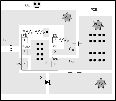
10.2 Layout Examples
 Figure 44. Example of Proper PCB Layout
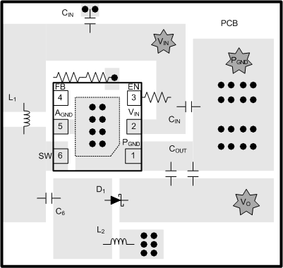
 The layout guidelines described for the LM2735 Boost-Converter are applicable to the SEPIC Converter. Figure 45 shows a proper PCB layout for a SEPIC Converter.
 Figure 45. SEPIC PCB Layout