ZHCSH29B April 2017 – December 2018 LP87524B-Q1 , LP87524J-Q1 , LP87524P-Q1
PRODUCTION DATA.
- 1 特性
- 2 應用
- 3 說明
- 4 修訂歷史記錄
- 5 Pin Configuration and Functions
- 6 Specifications
-
7 Detailed Description
- 7.1 Overview
- 7.2 Functional Block Diagram
- 7.3
Feature Descriptions
- 7.3.1 DC-DC Converters
- 7.3.2 Sync Clock Functionality
- 7.3.3 Power-Up
- 7.3.4 Regulator Control
- 7.3.5 Enable and Disable Sequences
- 7.3.6 Device Reset Scenarios
- 7.3.7 Diagnosis and Protection Features
- 7.3.8 GPIO Signal Operation
- 7.3.9 Digital Signal Filtering
- 7.4 Device Functional Modes
- 7.5 Programming
- 7.6
Register Maps
- 7.6.1
Register Descriptions
- 7.6.1.1 OTP_REV
- 7.6.1.2 BUCK0_CTRL1
- 7.6.1.3 BUCK1_CTRL1
- 7.6.1.4 BUCK2_CTRL1
- 7.6.1.5 BUCK3_CTRL1
- 7.6.1.6 BUCK0_VOUT
- 7.6.1.7 BUCK0_FLOOR_VOUT
- 7.6.1.8 BUCK1_VOUT
- 7.6.1.9 BUCK1_FLOOR_VOUT
- 7.6.1.10 BUCK2_VOUT
- 7.6.1.11 BUCK2_FLOOR_VOUT
- 7.6.1.12 BUCK3_VOUT
- 7.6.1.13 BUCK3_FLOOR_VOUT
- 7.6.1.14 BUCK0_DELAY
- 7.6.1.15 BUCK1_DELAY
- 7.6.1.16 BUCK2_DELAY
- 7.6.1.17 BUCK3_DELAY
- 7.6.1.18 GPIO2_DELAY
- 7.6.1.19 GPIO3_DELAY
- 7.6.1.20 RESET
- 7.6.1.21 CONFIG
- 7.6.1.22 INT_TOP1
- 7.6.1.23 INT_TOP2
- 7.6.1.24 INT_BUCK_0_1
- 7.6.1.25 INT_BUCK_2_3
- 7.6.1.26 TOP_STAT
- 7.6.1.27 BUCK_0_1_STAT
- 7.6.1.28 BUCK_2_3_STAT
- 7.6.1.29 TOP_MASK1
- 7.6.1.30 TOP_MASK2
- 7.6.1.31 BUCK_0_1_MASK
- 7.6.1.32 BUCK_2_3_MASK
- 7.6.1.33 SEL_I_LOAD
- 7.6.1.34 I_LOAD_2
- 7.6.1.35 I_LOAD_1
- 7.6.1.36 PGOOD_CTRL1
- 7.6.1.37 PGOOD_CTRL2
- 7.6.1.38 PGOOD_FLT
- 7.6.1.39 PLL_CTRL
- 7.6.1.40 PIN_FUNCTION
- 7.6.1.41 GPIO_CONFIG
- 7.6.1.42 GPIO_IN
- 7.6.1.43 GPIO_OUT
- 7.6.1
Register Descriptions
- 8 Application and Implementation
- 9 Power Supply Recommendations
- 10Layout
- 11器件和文檔支持
- 12機械、封裝和可訂購信息
8.2.3 Application Curves
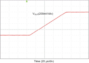
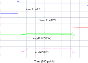
Measurements are done using typical application set up with connections shown in Figure 22 (snubber components included when VIN > 4 V). Graphs may not reflect the OTP default settings. Unless otherwise specified: VIN = 3.7 V, VOUT = 1 V, V(NRST) = 1.8 V, TA = 25°C, ƒSW = 4 MHz, L = 0.47 µH (TOKO DFE252012PD-R47M), COUT = 22 µF / phase, and CPOL = 22 µF / phase. Measurements are done using connections in the Typical Application.
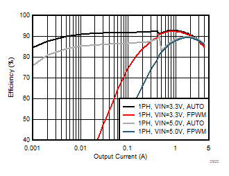
| VOUT = 1.8 V |
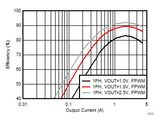
| VIN = 5 V |
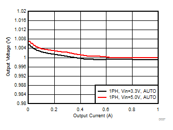 Figure 27. Output Voltage vs Load Current in PFM/PWM Mode
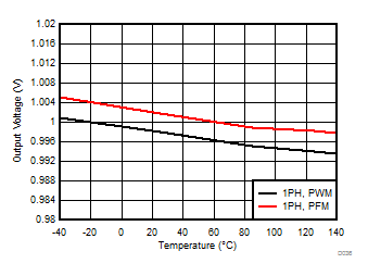
| Load = 1 A (PWM) and 0.1 A (PFM) | ||
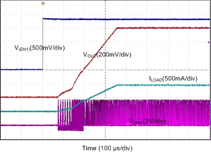
| RLOAD = 1 Ω |
(1-Phase Output)
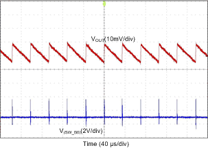
| IOUT = 10 mA |
(1-Phase Output)
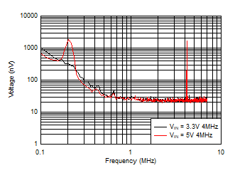
| VOUT = 1 V | No load | RBW/VBW = 10 Hz |
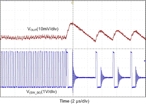
(1-Phase Output)
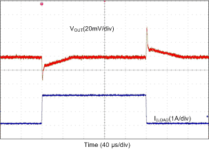
| IOUT = 0.1 A → 2 A → 0.1 A | TR = TF = 1 µs |
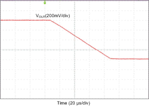
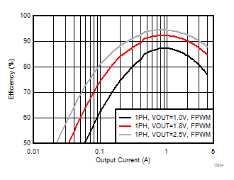
| VIN = 3.3 V |
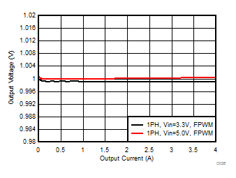
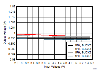
| VOUT = 1 V | Load = 1 A |
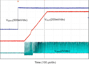
| IOUT = 0 A |
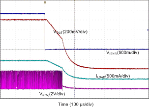
| RLOAD = 1 Ω |
(1-Phase Output)
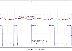
| IOUT = 200 mA |
(1-Phase Output)
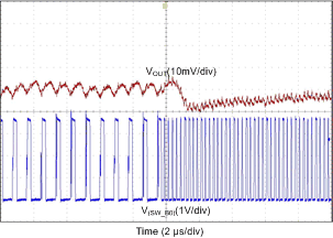
(1-Phase Output)
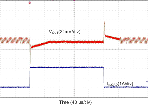
| IOUT = 0.1 A → 2 A → 0.1 A | TR = TF = 1 µs |
(1-Phase Output)
