SLVSGC3 May 2020 DRV8210P
PRODUCTION DATA
- 1 Features
- 2 Applications
- 3 Description
- 4 Revision History
- 5 Device Comparison
- 6 Pin Configuration and Functions
- 7 Specifications
- 8 Detailed Description
- 9 Application and Implementation
- 10Power Supply Recommendations
- 11Layout
- 12Device and Documentation Support
- 13Mechanical, Packaging, and Orderable Information
6 Pin Configuration and Functions
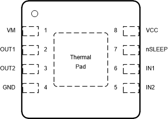
 Figure 6-1 DRV8210P DSG Package8-Pin WSONTop View
Table 6-1 Pin Functions
| PIN | TYPE | DESCRIPTION | |
|---|---|---|---|
| NAME | NO. | ||
| GND | 4 | PWR | Device ground. Connect to system ground. |
| IN1 | 6 | I | H-bridge control input. See Section 8.3.2. Internal pulldown resistor. |
| IN2 | 5 | I | H-bridge control input. See Section 8.3.2. Internal pulldown resistor. |
| nSLEEP | 7 | I | Sleep mode input. Set this pin to logic high to enable the device. Set this pin to logic low to go to low-power sleep mode. Internal pulldown resistor. |
| OUT1 | 2 | O | H-bridge output. Connect to the motor or other load. |
| OUT2 | 3 | O | H-bridge output. Connect to the motor or other load. |
| VM | 1 | PWR | Motor power supply. Bypass this pin to the GND pin with a 0.1-μF ceramic capacitor as well as sufficient bulk capacitance rated for VM. |
| VCC | 8 | PWR | Logic power supply. Bypass this pin to the GND pin with a 0.1-μF ceramic capacitor rated for VCC. |
| PAD | — | — | Thermal pad. Connect to system ground. |