SLVK235 September 2025 CDCLVP111-SEP
8 Single-Event Transients (SET)
SET are defined as heavy-ion-induced transients upsets on the output Q0 – Q9 CDCLVP111-SEP.
Testing was performed at room temperature (no external temperature control applied). The heavy-ions species used for the SET testing were 84Kr, 40Ar and 20Ne for a LETEFF of 2.79 – 44.12MeVcm2/mg, for more details refer to Ion LETEFF and Range in Silicon. Flux of 1 × 10⁵- 1 × 10⁶ ions × cm2/s and a fluence of 1 × 10⁷ ions/cm2, per run were used for the SET characterization discussed on this chapter.
The SET characterization was performed at room temperature over two units. Several heavy-ion species were used (and some at multiple angles of incidence) to provide a LETEFF ranging from 2.79 to 44.12MeV·cm2/mg. In most cases, for each condition, two back-to-back identical runs were conducted for statistical purposes.
To capture different types of SET events, three different trigger types were used for the characterization: window, runt, and pulse width triggers (positive and negative). The purpose of each trigger mode is as follows:
- Window: Captures any deviation of the magnitude of the pulse.
- Runt: Captures any deviation from VOH and VOL levels. The levels are adjusted with voltages and frequency levels.
- Pulse width: Captures any
deviation of the duty cycle.
- Positive: Captures any instance where the on-time is higher than expected.
- Negative: Captures any instance where the on-time is lower than expected.
Trigger type and signal for all scopes used is presented in Table 8-1.
| Scope Model | Trigger Signal | Trigger Type |
|---|---|---|
| DPO7254C | Q0-DIFF | Pulse Width - Positive |
| Pulse Width - Negative | ||
| Window | ||
| Runt | ||
| Q9-DIFF | Pulse Width - Positive | |
| Pulse Width - Negative | ||
| Window | ||
| Runt |
To be able to capture events occurring in the input multiplexer, the two input clocks were set at different frequencies. The differential pair CLK0 frequency was changed between 200MHz and 1200MHz and the differential input pair CLK1 was held constant at 100MHz during all tests. Any transient event on the input multiplexer change the frequency and the pulse width trigger mode captures these events. No SET events on the input multiplexer have been observed during any of the test runs. Table 8-3 lists the clock amplitudes and offset for the MIN (2.375V) and MAX (3.800V) voltages used during the characterization.
| Voltage | VCC-VEE (V) | VEE-GND (V) | CLK |VIH-VIL| Input Amplitude of CLK0, CLK1 (mV) | CLK Offset (V) |
|---|---|---|---|---|
| MIN | 2.375 | 2 | 500 | 0.625 |
| MAX | 3.8 | 2 | 500 | -0.8 |
Pulse Width Trigger
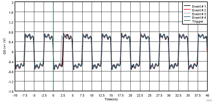
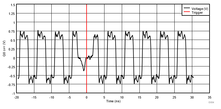
Figure 8-1 shows the cross-sectional plot for the positive pulse width trigger. Additionally, Figure 8-2 shows the cross-sectional plot for the positive pulse width trigger. Table 8-4 and Table 8-6 list the test conditions used for all the SET runs positive and negative pulse width trigger type, respectively. Figure 8-4 and Figure 8-5 show examples of the typical voltage versus time events for the positive and negative pulse width trigger type, respectively. All observed events were transitory and quickly recovered to normal operation. Equation 8-1 describes the cross-sectional calculation method.
 Figure 8-1 CDCLVP111-SEP Pulse Width -
Positive Trigger Weibul Fit
Figure 8-1 CDCLVP111-SEP Pulse Width -
Positive Trigger Weibul FitThe equation below describes the cross-sectional calculation method, which was used for all Weibull fits for all SET trigger analysis. Table 8-3 shows the Weibull parameters for positive pulse width trigger. Table 8-5 shows the Weibull parameters for the negative pulse width trigger. Table 8-8 shows the Weibull parameters for the runt trigger.
| Parameter | Value |
|---|---|
| Cross-Section (cm2) | 1.35 × 10-? |
| Onset (MeV-cm2/mg) | 0.95 |
| W | 15.69 |
| S | 3.47 |
| Run | Device | Ion | Effective LET (MeV·cm2/mg) | Effective Fluence (Total amount of Ions) | VCC-VEE (V) | Trigger Settings | Number of Event |
|---|---|---|---|---|---|---|---|
| 3 | 2 | 20Ne | 2.79 | 9.98 × 10⁵ | 2.375 | UL = 2.6ns ; LL = 2.46ns | 0 |
| 4 | 2 | 40Ar | 8.68 | 1.00 × 10⁶ | 2.375 | UL = 2.6ns ; LL = 2.46ns | 2 |
| 5 | 2 | 40Ar | 8.68 | 1.00 × 10⁶ | 2.375 | UL = 2.6ns ; LL = 2.46ns | 1 |
| 6 | 2 | 40Ar | 8.68 | 9.99 × 10⁵ | 3.8 | UL = 2.6ns ; LL = 2.46ns | 0 |
| 7 | 2 | 40Ar | 12.39 | 1.01 × 10⁶ | 2.375 | UL = 2.6ns ; LL = 2.46ns | 4 |
| 8 | 2 | 40Ar | 12.39 | 1.00 × 10⁶ | 2.375 | UL = 2.6ns ; LL = 2.46ns | 2 |
| 9 | 2 | 84Kr | 30.79 | 1.00 × 10⁶ | 2.375 | UL = 2.6ns ; LL = 2.48ns | 18 |
| 10 | 2 | 84Kr | 30.79 | 1.00 × 10⁶ | 2.375 | UL = 2.6ns ; LL = 2.48ns | 9 |
| 11 | 2 | 84Kr | 44.12 | 1.00 × 10⁶ | 2.375 | UL = 2.58ns ; LL = 2.48ns | 10 |
| 12 | 2 | 84Kr | 44.12 | 1.00 × 10⁶ | 2.375 | UL = 2.58ns ; LL = 2.48ns | 13 |
| 13 | 3 | 84Kr | 44.12 | 9.99 × 10⁵ | 3.8 | UL = 2.6ns ; LL = 2.46ns | 12 |
| 14 | 3 | 84Kr | 44.12 | 9.98 × 10⁵ | 2.375 | UL = 2.6ns ; LL = 2.46ns | 9 |
| 15 | 3 | 84Kr | 44.12 | 2.19 × 10⁵ | 2.375 | UL = 2.6ns ; LL = 2.46ns | 0 |
| 16 | 3 | 84Kr | 44.12 | 1.00 × 10⁶ | 2.375 | UL = 2.6ns ; LL = 2.46ns | 10 |
 Figure 8-2 CDCLVP111-SEP Pulse Width -
Negative Trigger Weibull Fit
Figure 8-2 CDCLVP111-SEP Pulse Width -
Negative Trigger Weibull Fit| Parameter | Value |
|---|---|
| Cross-Section (cm2) | 1.32 × 10-? |
| Onset (MeV-cm2/mg) | 0.56 |
| W | 15.36 |
| S | 3.58 |
| Run | Device | Ion | Effective LET (MeV·cm2/mg) | Effective Fluence (Total amount of Ions) | VCC-VEE (V) | Trigger Settings | Number of Event |
|---|---|---|---|---|---|---|---|
| 19 | 2 | 40Ar | 8.68 | 9.96 x 10⁵ | 2.375 | UL = 2.6ns ; LL = 2.46ns | 1 |
| 20 | 2 | 40Ar | 8.68 | 9.98 x 10⁵ | 2.375 | UL = 2.6ns ; LL = 2.46ns | 3 |
| 21 | 2 | 40Ar | 12.39 | 1.00 x 10⁶ | 2.375 | UL = 2.6ns ; LL = 2.46ns | 2 |
| 22 | 2 | 40Ar | 12.39 | 1.00 x 10⁶ | 2.375 | UL = 2.6ns ; LL = 2.46ns | 3 |
| 23 | 2 | 84Kr | 30.79 | 1.00 x 10⁶ | 2.375 | UL = 2.58ns ; LL = 2.48ns | 11 |
| 24 | 2 | 84Kr | 30.79 | 9.96 x 10⁵ | 2.375 | UL = 2.58ns ; LL = 2.48ns | 13 |
| 25 | 2 | 84Kr | 30.79 | 1.00 x 10⁶ | 2.375 | UL = 2.58ns ; LL = 2.48ns | 12 |
| 26 | 2 | 84Kr | 44.12 | 9.98 x 10⁵ | 2.375 | UL = 2.6ns ; LL = 2.46ns | 15 |
| 27 | 2 | 84Kr | 44.12 | 1.00 x 10⁶ | 2.375 | UL = 2.6ns ; LL = 2.46ns | 15 |
| 28 | 3 | 84Kr | 44.12 | 1.00 x 10⁶ | 3.8 | UL = 2.6ns ; LL = 2.46ns | 10 |
| 29 | 3 | 84Kr | 44.12 | 9.98 x 10⁵ | 2.375 | UL = 2.6ns ; LL = 2.46ns | 14 |
| 30 | 3 | 84Kr | 44.12 | 1.00 x 10⁶ | 2.375 | UL = 2.6ns ; LL = 2.46ns | 12 |
Window Trigger
No SET was observed at the minimum voltage, maximum voltage and 200MHz clock frequency. However, the user can calculate the 99% confidence upper-bound cross section by using the MFTF method as described in Section A.2 and combining (or summing) the fluence of the all runs performed under the same conditions (see Equation 8-2 and Equation 8-1). The SET conditions and event results are shown in Table 8-7.
| Run | Device | Ion | Effective LET (MeVcm2/mg) | Effective Fluence (Total amount of Ions) | VCC-VEE (V) | Trigger Settings | Number of Events |
|---|---|---|---|---|---|---|---|
| 33 | 2 | 20Ne | 2.79 | 1.00 × 10⁶ | 2.375 | UL = 810mV ; LL = -830mV | 0 |
| 34 | 2 | 20Ne | 2.79 | 9.99 × 10⁵ | 2.375 | UL = 810mV ; LL = -830mV | 0 |
| 35 | 2 | 40Ar | 12.39 | 1.00 × 10⁶ | 2.375 | UL = 810mV ; LL = -830mV | 0 |
| 36 | 2 | 40Ar | 12.39 | 1.00 × 10⁶ | 2.375 | UL = 810mV ; LL = -830mV | 0 |
| 37 | 2 | 84Kr | 30.79 | 9.97 × 10⁵ | 2.375 | UL = 810mV ; LL = -830mV | 0 |
| 38 | 2 | 84Kr | 30.79 | 9.95 × 10⁵ | 2.375 | UL = 810mV ; LL = -830mV | 0 |
| 39 | 2 | 84Kr | 44.12 | 1.00 × 10⁶ | 2.375 | UL = 852mV ; LL = -850mV | 0 |
| 40 | 2 | 84Kr | 44.12 | 1.00 × 10⁶ | 2.375 | UL = 852mV ; LL = -850mV | 0 |
| 41 | 3 | 84Kr | 44.12 | 1.00 × 10⁶ | 3.8 | UL = 1.12V ; LL = -1.12V | 0 |
| 42 | 3 | 84Kr | 44.12 | 9.98 × 10⁵ | 3.8 | UL = 1.12V ; LL = -1.12V | 0 |
| 43 | 3 | 84Kr | 44.12 | 9.96 × 10⁵ | 2.375 | UL = 810mV ; LL = -770mV | 0 |
Runt Trigger
Figure 8-3 shows the cross-sectional plot for the runt trigger. Table 8-8 lists the parameters for the Weibul Fit for runt trigger. Table 8-9 list the test conditions used for all the SET runs with Runt trigger type.
 Figure 8-3 CDCLVP111-SEP Runt Trigger
Weibull FIt
Figure 8-3 CDCLVP111-SEP Runt Trigger
Weibull FIt| Parameter | Value |
|---|---|
| Cross-Section (cm2) | 1.17 × 10-? |
| Onset (MeV-cm2/mg) | 1.24 |
| W | 15.91 |
| s | 5.08 |
| Run | Device | Ion | Effective LET (MeVcm2/mg) | Effective Fluence (Total amount of Ions) | VCC-VEE (V) | Trigger Settings | Number of Events |
|---|---|---|---|---|---|---|---|
| 48 | 2 | 20Ne | 2.79 | 1.00 × 10⁶ | 2.375 | UL = 610mV; LL = -630mV | 0 |
| 49 | 2 | 20Ne | 2.79 | 1.00 × 10⁶ | 2.375 | UL = 610mV; LL = -630mV | 0 |
| 50 | 2 | 40Ar | 8.68 | 1.00 × 10⁶ | 2.375 | UL = 450mV; LL = -400mV | 1 |
| 51 | 2 | 40Ar | 8.68 | 1.01 × 10⁶ | 2.375 | UL = 450mV; LL = -400mV | 0 |
| 52 | 2 | 40Ar | 12.39 | 9.97 × 10⁵ | 2.375 | UL = 610mV; LL = -630mV | 0 |
| 53 | 2 | 40Ar | 12.39 | 1.02 × 10⁶ | 2.375 | UL = 610mV; LL = -630mV | 2 |
| 54 | 2 | 40Ar | 12.39 | 1.00 × 10⁶ | 2.375 | UL = 450mV; LL = -400mV | 4 |
| 55 | 2 | 40Ar | 12.39 | 9.97 × 10⁵ | 2.375 | UL = 450mV; LL = -400mV | 0 |
| 56 | 2 | 84Kr | 30.79 | 9.96 × 10⁵ | 2.375 | UL = 350mV; LL = -290mV | 8 |
| 57 | 2 | 84Kr | 30.79 | 9.97 × 10⁵ | 2.375 | UL = 350mV; LL = -290mV | 8 |
| 58 | 2 | 84Kr | 44.12 | 1.00 × 10⁶ | 2.375 | UL = 740mV; LL = -680mV | 1 |
| 59 | 2 | 84Kr | 44.12 | 1.00 × 10⁶ | 2.375 | UL = 350mV; LL = -290mV | 3 |
| 60 | 2 | 84Kr | 44.12 | 1.00 × 10⁶ | 2.375 | UL = 350mV; LL = -290mV | 5 |
| 61 | 3 | 84Kr | 44.12 | 3.67 × 10⁵ | 3.8 | UL = 350mV; LL = -290mV | 20 |
| 62 | 3 | 84Kr | 44.12 | 1.00 × 10⁶ | 3.8 | UL = 710mV; LL = -730mV | 55 |
| 63 | 3 | 84Kr | 44.12 | 1.00 × 10⁶ | 2.375 | UL = 810mV; LL = -770mV | 0 |
| 64 | 3 | 84Kr | 44.12 | 1.00 × 10⁶ | 2.375 | UL = 610mV; LL = -630mV | 3 |
| 65 | 3 | 84Kr | 44.12 | 1.00 × 10⁶ | 2.375 | UL = 610mV; LL = -630mV | 2 |
Time Domain SET Examples
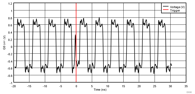
The positive pulse-width trigger events in Figure 8-4 only show a small deviation from the normal clock output. The negative pulse-width trigger event captured in Figure 8-5 shows a violation of the negative pulse width (time), which can also be considered as a VOL violation. Some events captured with the runt trigger are also captured with the pulse-width trigger and vice versa. Figure 8-6 shows this behavior where a runt event can also be interpreted as a positive pulse-width violation.. At 200MHz all events recover within just one clock cycle; however, at 1.2GHz, two clock cycles are required for recovery. The events were local 54.55% of the time, affecting only the differential pair Q0. The other 45.45% of the time, the event has a global effect on the Q0 and Q9 differential pair.
 Figure 8-4 Time Domain Plot of Events on
Run 7 Positive Pulse Width Trigger
 Figure 8-5 Time Domain Plot of Event 2 on
Run 32 Negative Pulse Width Trigger
 Figure 8-6 Time Domain Plot of Event 6 on
Run 56 Runt Trigger