ZHCS276F September 2011 – February 2025 DRV8818
PRODUCTION DATA
- 1
- 1 特性
- 2 應(yīng)用
- 3 說明
- 4 Pin Configuration and Functions
- 5 Specifications
- 6 Detailed Description
- 7 Application and Implementation
- 8 Device and Documentation Support
- 9 Revision History
- 10Mechanical, Packaging, and Orderable Information
封裝選項
機械數(shù)據(jù) (封裝 | 引腳)
- PWP|28
散熱焊盤機械數(shù)據(jù) (封裝 | 引腳)
- PWP|28
訂購信息
6.3.3 Decay Mode
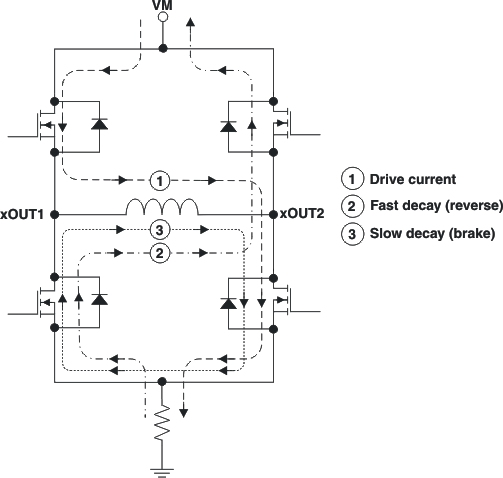
During PWM current chopping, the H-bridge is enabled to drive through the motor winding until the PWM current chopping threshold is reached. This is shown in Figure 6-2, Item 1. The current flow direction shown indicates positive current flow in the step table below.
Once the chopping current threshold is reached, the H-bridge can operate in two different states, fast decay or slow decay.
In fast decay mode, once the PWM chopping current level has been reached, the H-bridge reverses state to allow winding current to flow in a reverse direction. If synchronous rectification is enabled (SRn pin logic low), the opposite FETs are turned on; as the winding current approaches zero, the bridge is disabled to prevent any reverse current flow. If SRn is high, current is recirculated through the body diodes, or through external Schottky diodes. Fast-decay mode is shown in Figure 6-2, Item 2.
In slow-decay mode, winding current is re-circulated by enabling both of the low-side FETs in the bridge. This is shown in Figure 6-2, Item 3.
If SRn is high, current is recirculated only through the body diodes, or through external Schottky diodes. In this case fast decay is always used.
 Figure 6-2 Decay Mode
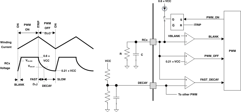
The DRV8818 also supports a mixed decay mode. Mixed decay mode begins as fast decay, but after a period of time switches to slow decay mode for the remainder of the fixed off time.
Fast and mixed decay modes are only active if the current through the winding is decreasing; if the current is increasing, then slow decay is always used.
Which decay mode is used is selected by the voltage on the DECAY pin. If the voltage is greater than 0.6 × VCC, slow decay mode is always used. If DECAY is less than 0.21 × VCC, the device operates in fast decay mode when the current through the winding is decreasing. If the voltage is between these levels, mixed decay mode is enabled.
In mixed decay mode, the voltage on the DECAY pin sets the point in the cycle that the change to slow decay mode occurs. This time can be approximated by:

Mixed decay mode is only used while the current though the winding is decreasing; slow decay is used while the current is increasing.
Operation of the blanking, fixed off time, and mixed decay mode is illustrated in Figure 6-3.
 Figure 6-3 PWM