ZHCSHA0E January 2018 – March 2021 DRV10974
PRODUCTION DATA
- 1 特性
- 2 應用
- 3 說明
- 4 Revision History
- 5 Pin Configuration and Functions
- 6 Specifications
-
7 Detailed Description
- 7.1 Overview
- 7.2 Functional Block Diagram
- 7.3 Feature Description
- 7.4 Device Functional Modes
- 8 Application and Implementation
- 9 Power Supply Recommendations
- 10Layout
- 11Device and Documentation Support
- 12Mechanical, Packaging, and Orderable Information
封裝選項
機械數據 (封裝 | 引腳)
散熱焊盤機械數據 (封裝 | 引腳)
訂購信息
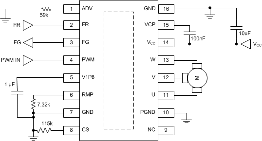
8.2 Typical Application
 Figure 8-1 Typical Application Schematic
Table 8-1 Recommended External Components
| NODE 1 | NODE 2 | COMPONENT |
|---|---|---|
| VCC | GND | 10-μF, 25-V ceramic capacitor tied from VCC to ground |
| VCP | VCC | 100-nF, 10-V ceramic capacitor tied from VCP to VCC |
| V1P8 | GND | 1-μF ±30%, 6.3-V ceramic capacitor tied from V1P8 to ground |
| RMP | GND | 1%, 1/8 watt resistor tied from RMP to ground to set the desired acceleration profile |
| CS | GND | 1%, 1/8-watt resistor tied from CS to ground to set the desired current limit |
| ADV | GND | 1%, 1/8-watt resistor tied from ADV to ground to set the desired lead angle (time) |