SLUA778A June 2016 – July 2016 UCC21520 , UCC21520-Q1 , UCC21540
2 Internal Shoot-Through with Mismatched Propagation Delay
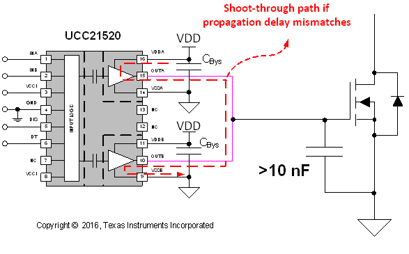
The propagation delay mismatch will introduce internal shoot-through if the two output channels are paralleled. Figure 2 shows the simplified circuit diagram with UCC21520 two output channels in parallel driving a heavy load. In this example, it is assumed that the channel A turn-on happens earlier than channel B, or channel A turn-off later than channel B. The red dotted line shows the shoot-through path which shorts VDD to ground with very small impedance, which is typically 1.5 Ω combining pull-up and pull-down resistance. Therefore, there will be large current flow through the gate driver device, and will result in additional internal heat. The estimated loss per cycle can be calculated by:

- PST: Shoot-through introduced extra loss;
- VDD: Supply voltage on VDDA and VDDB;
- IST: Shoot-through current, decided by the pull-up and pull-down circuit design;
- tDM_Rise: Propagation delay matching at rising edge;
- tDM_Fall: Propagation delay matching at falling edge;
- fSW: switching frequency;
where
To make sure UCC21520 two channels can be used in parallel, it is essential to quantify the delay matching data at different VDD voltage and temperature.
 Figure 2. Internal Shoot-Through with Mismatched Propagation Delay Between Output Channels