ZHCSGN5B March 2017 – July 2018 LP8863-Q1
PRODUCTION DATA.
- 1 特性
- 2 應用
- 3 說明
- 4 修訂歷史記錄
- 5 Device Comparison Table
- 6 Pin Configuration and Functions
-
7 Specifications
- 7.1 Absolute Maximum Ratings
- 7.2 ESD Ratings
- 7.3 Recommended Operating Conditions
- 7.4 Thermal Information
- 7.5 Electrical Characteristics
- 7.6 Protection Electrical Characteristics
- 7.7 LED Current Sink and LED PWM Electrical Characteristics
- 7.8 Power-Line FET and RISENSE Electrical Characteristics
- 7.9 Input PWM Electrical Characteristics
- 7.10 Boost Converter Electrical Characteristics
- 7.11 Oscillator
- 7.12 Charge Pump
- 7.13 Logic Interface Characteristics
- 7.14 Timing Requirements for SPI Interface
- 7.15 Timing Requirements for I2C Interface
- 7.16 Typical Characteristics
-
8 Detailed Description
- 8.1 Overview
- 8.2 Functional Block Diagram
- 8.3 Feature Description
- 8.4 Device Functional Modes
- 8.5 Programming
- 8.6
Register Maps
- 8.6.1
FullMap Registers
- 8.6.1.1 BL_MODE Register (Offset = 20h) [reset = 300h]
- 8.6.1.2 DISP_BRT Register (Offset = 28h) [reset = 0h]
- 8.6.1.3 GROUPING1 Register (Offset = 30h) [reset = 0h]
- 8.6.1.4 GROUPING2 Register (Offset = 32h) [reset = 0h]
- 8.6.1.5 USER_CONFIG1 Register (Offset = 40h) [reset = 8B0h]
- 8.6.1.6 USER_CONFIG2 Register (Offset = 42h) [reset = 0h]
- 8.6.1.7 INTERRUPT_ENABLE_3 Register (Offset = 4Eh) [reset = 200Ah]
- 8.6.1.8 INTERRUPT_ENABLE_1 Register (Offset = 50h) [reset = A02Ah]
- 8.6.1.9 INTERRUPT_ENABLE_2 Register (Offset = 52h) [reset = 80h]
- 8.6.1.10 INTERRUPT_STATUS_1 Register (Offset = 54h) [reset = 0h]
- 8.6.1.11 INTERRUPT_STATUS_2 Register (Offset = 56h) [reset = 0h]
- 8.6.1.12 INTERRUPT_STATUS_3 Register (Offset = 58h) [reset = 0h]
- 8.6.1.13 JUNCTION_TEMPERATURE Register (Offset = E8h) [reset = 100h]
- 8.6.1.14 TEMPERATURE_LIMIT_HIGH Register (Offset = ECh) [reset = 7Dh]
- 8.6.1.15 TEMPERATURE_LIMIT_LOW Register (Offset = EEh) [reset = 69h]
- 8.6.1.16 CLUSTER1_BRT Register (Offset = 13Ch) [reset = FFFFh]
- 8.6.1.17 CLUSTER2_BRT Register (Offset = 148h) [reset = FFFFh]
- 8.6.1.18 CLUSTER3_BRT Register (Offset = 154h) [reset = FFFFh]
- 8.6.1.19 CLUSTER4_BRT Register (Offset = 160h) [reset = FFFFh]
- 8.6.1.20 CLUSTER5_BRT Register (Offset = 16Ch) [reset = FFFFh]
- 8.6.1.21 BRT_DB_CONTROL Register (Offset = 178h) [reset = 0h]
- 8.6.1.22 LED0_CURRENT Register (Offset = 1C2h) [reset = FFFh]
- 8.6.1.23 LED1_CURRENT Register (Offset = 1C4h) [reset = FFFh]
- 8.6.1.24 LED2_CURRENT Register (Offset = 1C6h) [reset = FFFh]
- 8.6.1.25 LED3_CURRENT Register (Offset = 1C8h) [reset = FFFh]
- 8.6.1.26 LED4_CURRENT Register (Offset = 1CAh) [reset = FFFh]
- 8.6.1.27 LED5_CURRENT Register (Offset = 1CCh) [reset = FFFh]
- 8.6.1.28 BOOST_CONTROL Register (Offset = 288h) [reset = 1C0h]
- 8.6.1.29 SHORT_THRESH Register (Offset = 28Ah) [reset = 2882h]
- 8.6.1.30 FSM_DIAGNOSTICS Register (Offset = 2A4h) [reset = 0h]
- 8.6.1.31 PWM_INPUT_DIAGNOSTICS Register (Offset = 2A6h) [reset = 0h]
- 8.6.1.32 PWM_OUTPUT_DIAGNOSTICS Register (Offset = 2A8h) [reset = 0h]
- 8.6.1.33 LED_CURR_DIAGNOSTICS Register (Offset = 2AAh) [reset = 0h]
- 8.6.1.34 ADAPT_BOOST_DIAGNOSTICS Register (Offset = 2ACh) [reset = 0h]
- 8.6.1.35 AUTO_DETECT_DIAGNOSTICS Register (Offset = 2AEh) [reset = 0h]
- 8.6.1
FullMap Registers
-
9 Application and Implementation
- 9.1 Application Information
- 9.2
Typical Applications
- 9.2.1
Full Feature Application for Display Backlight
- 9.2.1.1 Design Requirements
- 9.2.1.2
Detailed Design Procedure
- 9.2.1.2.1 Inductor Selection
- 9.2.1.2.2 Output Capacitor Selection
- 9.2.1.2.3 Input Capacitor Selection
- 9.2.1.2.4 Charge Pump Output Capacitor
- 9.2.1.2.5 Charge Pump Flying Capacitor
- 9.2.1.2.6 Output Diode
- 9.2.1.2.7 Switching FET
- 9.2.1.2.8 Boost Sense Resistor
- 9.2.1.2.9 Power-Line FET
- 9.2.1.2.10 Input Current Sense Resistor
- 9.2.1.2.11 Feedback Resistor Divider
- 9.2.1.2.12 Critical Components for Design
- 9.2.1.3 Application Curves
- 9.2.2 Application With Basic/Minimal Operation
- 9.2.3
SEPIC Mode Application
- 9.2.3.1 Design Requirements
- 9.2.3.2
Detailed Design Procedure
- 9.2.3.2.1 Inductor Selection
- 9.2.3.2.2 Coupling Capacitor Selection
- 9.2.3.2.3 Output Capacitor Selection
- 9.2.3.2.4 Input Capacitor Selection
- 9.2.3.2.5 Charge Pump Output Capacitor
- 9.2.3.2.6 Charge Pump Flying Capacitor
- 9.2.3.2.7 Switching FET
- 9.2.3.2.8 Output Diode
- 9.2.3.2.9 Switching Sense Resistor
- 9.2.3.2.10 Power-Line FET
- 9.2.3.2.11 Input Current Sense Resistor
- 9.2.3.2.12 Feedback Resistor Divider
- 9.2.3.2.13 Critical Components for Design
- 9.2.3.3 Application Curves
- 9.2.1
Full Feature Application for Display Backlight
- 10Power Supply Recommendations
- 11Layout
- 12器件和文檔支持
- 13機械、封裝和可訂購信息
8.3.2 Boost Controller
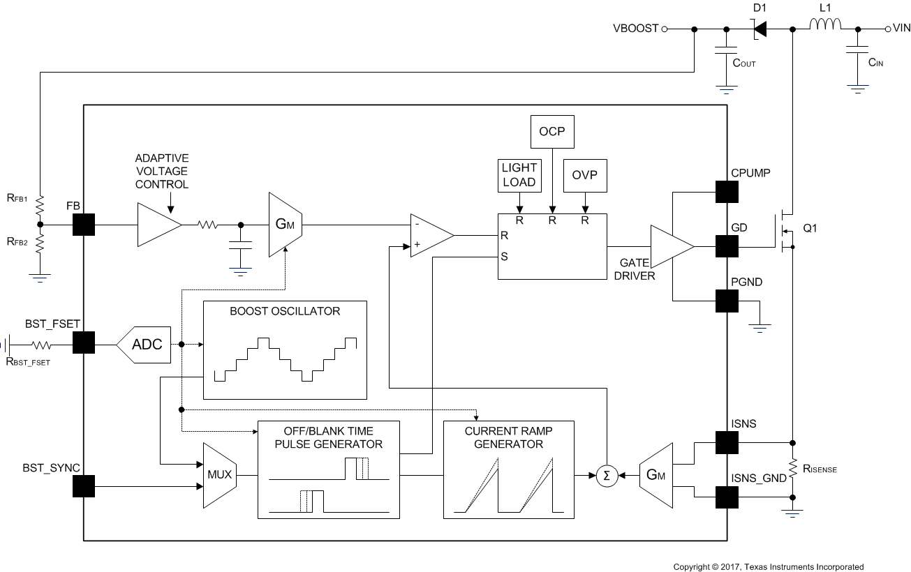
The LP8863-Q1 current-mode-controlled boost DC/DC controller generates the bias voltage for the LEDs. The boost is a current-mode-controlled topology with an 8-A cycle by cycle current limit. The boost converter senses the switch current and across the external sense resistor connected between ISNS and ISNSGND. A 25-mΩ sense resistor results in an 8-A cycle by cycle current limit.. Maximum boost voltage is configured with external FB-pin resistor divider connected between VOUT and FB. The FB-divider equation is described in Boost Adaptive Voltage Control.
 Figure 9. Boost Controller Block Diagram
 The boost switching frequency is adjustable from 300 kHz to 2.2 MHz via an external resistor at BST_FSET (see Table 2).
Table 2. Boost Frequency Selection
| R_BST_FSET (kΩ) | BOOST FREQUENCY (kHz) |
|---|---|
| 3.92 | 303 |
| 4.75 | 400 |
| 5.76 | 606 |
| 7.87 | 800 |
| 11 | 1000 |
| 17.8 | 1250 |
| 42.2 | 1667 |
| 140 | 2200 |