ZHCSKH7 November 2019 LDC1001
PRODUCTION DATA.
- 1 特性
- 2 應用
- 3 說明
- 4 修訂歷史記錄
- 5 Pin Configuration and Functions
- 6 Specifications
-
7 Detailed Description
- 7.1 Overview
- 7.2 Functional Block Diagram
- 7.3 Feature Description
- 7.4 Device Functional Modes
- 7.5 Programming
- 7.6
Register Maps
- 7.6.1
Register Description
- 7.6.1.1 Revision ID (Address = 0x00)
- 7.6.1.2 RP_MAX (Address = 0x01)
- 7.6.1.3 RP_MIN (Address = 0x02)
- 7.6.1.4 Watchdog Timer Frequency (Address = 0x03)
- 7.6.1.5 LDC Configuration (Address = 0x04)
- 7.6.1.6 Clock Configuration (Address = 0x05)
- 7.6.1.7 Comparator Threshold High LSB (Address = 0x06)
- 7.6.1.8 Comparator Threshold High MSB (Address = 0x07)
- 7.6.1.9 Comparator Threshold Low LSB (Address = 0x08)
- 7.6.1.10 Comparator Threshold Low MSB (Address = 0x09)
- 7.6.1.11 INTB Pin Configuration (Address = 0x0A)
- 7.6.1.12 Power Configuration (Address = 0x0B)
- 7.6.1.13 Status (Address = 0x20)
- 7.6.1.14 Proximity Data LSB (Address = 0x21)
- 7.6.1.15 Proximity Data MSB (Address = 0x22)
- 7.6.1.16 Frequency Counter LSB (Address = 0x23)
- 7.6.1.17 Frequency Counter Mid-Byte (Address = 0x24)
- 7.6.1.18 Frequency Counter MSB (Address = 0x25)
- 7.6.1
Register Description
- 8 Application and Implementation
- 9 Power Supply Recommendations
- 10Layout
- 11器件和文檔支持
- 12機械、封裝和可訂購信息
7.4.2.3 DRDY Mode
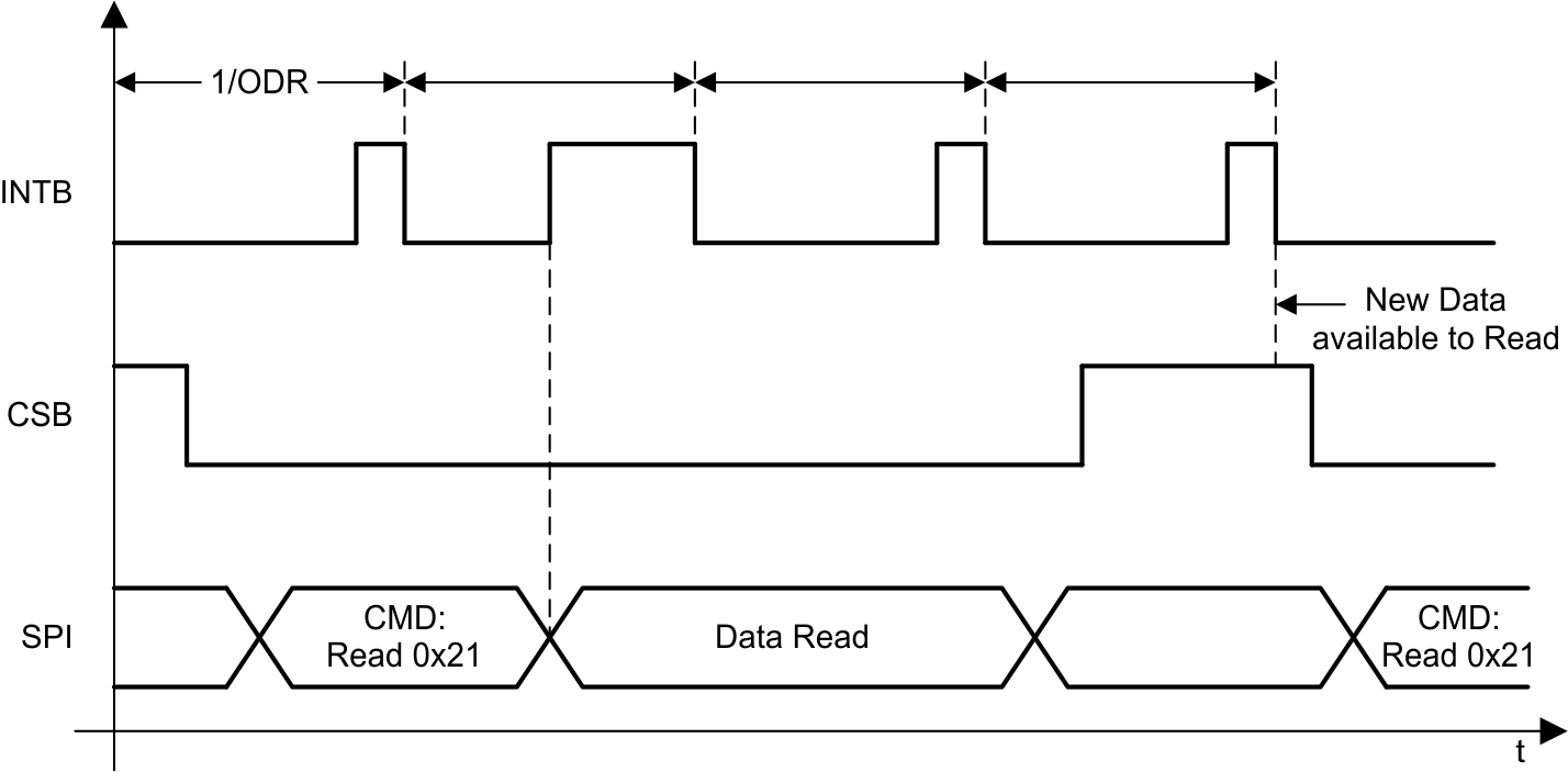
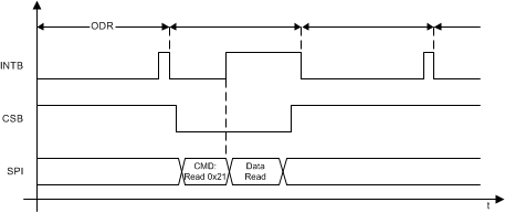
In DRDY mode, the INTB pin is asserted every time the conversion data is available and deasserted once the read command on register 0x21 is registered internally; if the read is in progress, the pin is pulsed instead. TI recommends to configure this setting after PWR_MODE has been set to 1 (the LDC1001 is in Active Mode).
 Figure 13. Behavior of INTB pin in DRDY Mode With SPI Extending Beyond Subsequent Conversions
  Figure 14. Behavior of INTB Pin in DRDY Mode With SPI Reading the Data Within Subsequent Conversion