ZHCSFZ1A January 2017 – July 2018 DRV8886
UNLESS OTHERWISE NOTED, this document contains PRODUCTION DATA.
- 1 特性
- 2 應用
- 3 說明
- 4 修訂歷史記錄
- 5 Pin Configuration and Functions
- 6 Specifications
-
7 Detailed Description
- 7.1 Overview
- 7.2 Functional Block Diagram
- 7.3
Feature Description
- 7.3.1 Stepper Motor Driver Current Ratings
- 7.3.2 PWM Motor Drivers
- 7.3.3 Microstepping Indexer
- 7.3.4 Current Regulation
- 7.3.5 Controlling RREF With an MCU DAC
- 7.3.6 Decay Modes
- 7.3.7 Blanking Time
- 7.3.8 Charge Pump
- 7.3.9 Linear Voltage Regulators
- 7.3.10 Logic and Multi-Level Pin Diagrams
- 7.3.11 Protection Circuits
- 7.4 Device Functional Modes
- 8 Application and Implementation
- 9 Power Supply Recommendations
- 10Layout
- 11器件和文檔支持
- 12機械、封裝和可訂購信息
封裝選項
機械數據 (封裝 | 引腳)
散熱焊盤機械數據 (封裝 | 引腳)
訂購信息
7.3.10 Logic and Multi-Level Pin Diagrams
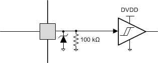
Figure 23 shows the input structure for the logic-level pins STEP, DIR, ENABLE, nSLEEP, and M1.
 Figure 23. Logic-Level Input Pin Diagram
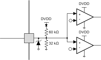
 The tri-level logic pins, M0 and TRQ, have the structure shown in Figure 24.
 Figure 24. Tri-Level Input Pin Diagram
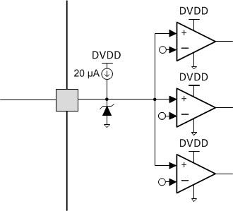
 The quad-level logic pin, DECAY, has the structure shown in Figure 25.
 Figure 25. Quad-Level Input Pin Diagram