ZHCSHZ0A April 2018 – July 2018 DRV8306
PRODUCTION DATA.
- 1 特性
- 2 應(yīng)用
- 3 說明
- 4 修訂歷史記錄
- 5 Pin Configuration and Functions
- 6 Specifications
-
7 Detailed Description
- 7.1 Overview
- 7.2 Functional Block Diagram
- 7.3
Feature Description
- 7.3.1 Three Phase Smart Gate Drivers
- 7.3.2 DVDD Linear Voltage Regulator
- 7.3.3 Pulse-by-Pulse Current Limit
- 7.3.4 Hall Comparators
- 7.3.5 FGOUT Signal
- 7.3.6 Pin Diagrams
- 7.3.7 Gate-Driver Protective Circuits
- 7.4 Device Functional Modes
- 8 Application and Implementation
- 9 Power Supply Recommendations
- 10Layout
- 11器件和文檔支持
- 12機(jī)械、封裝和可訂購信息
封裝選項(xiàng)
機(jī)械數(shù)據(jù) (封裝 | 引腳)
- RSM|32
散熱焊盤機(jī)械數(shù)據(jù) (封裝 | 引腳)
- RSM|32
訂購信息
8.2.1.3 Application Curves
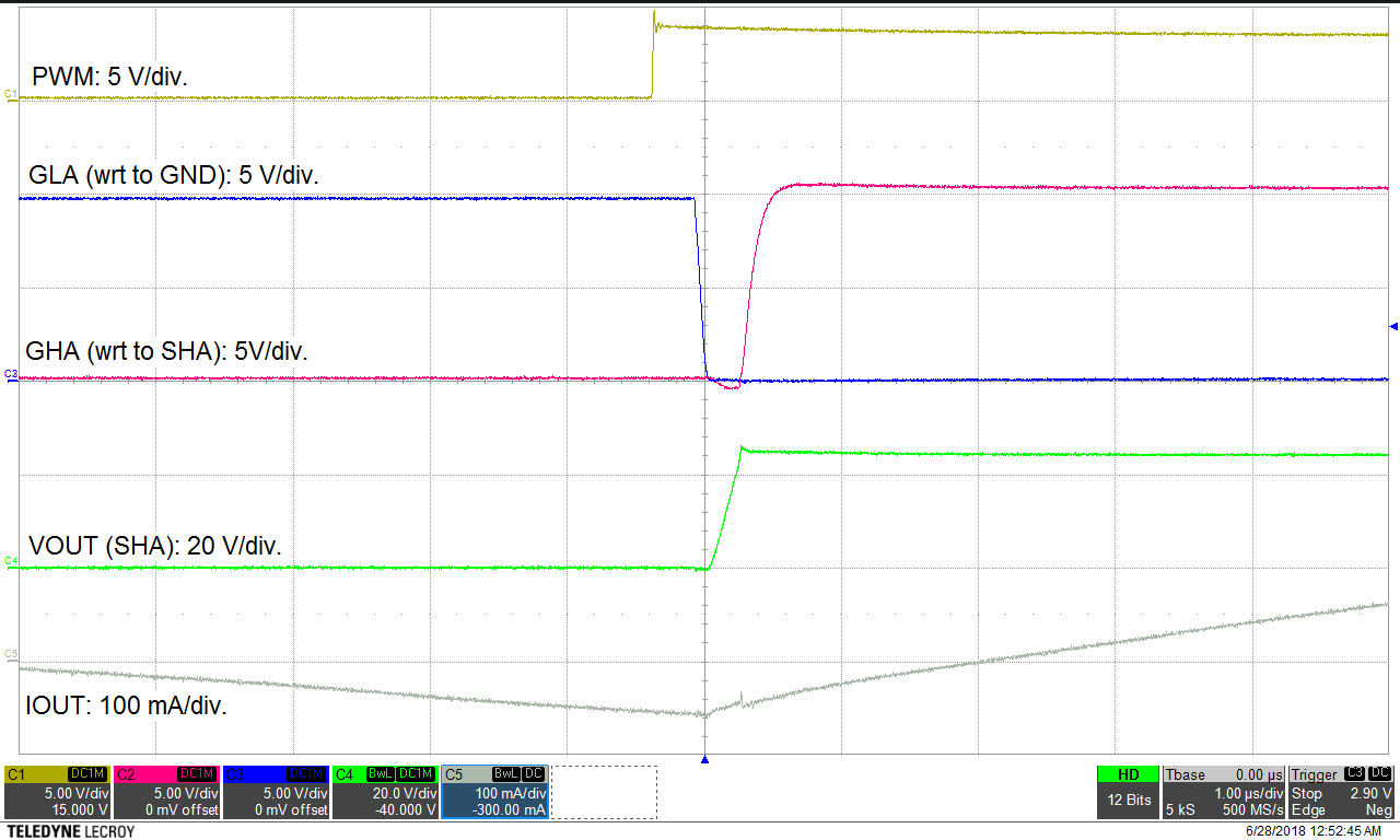 Figure 31. IDRIVE Maximum Setting
 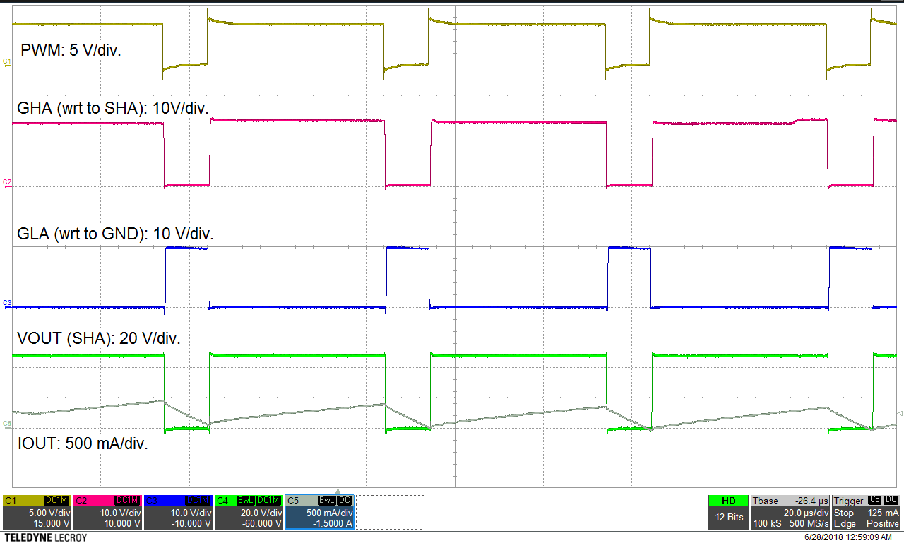 Figure 33. Gate Drive 80% Duty Cycle
 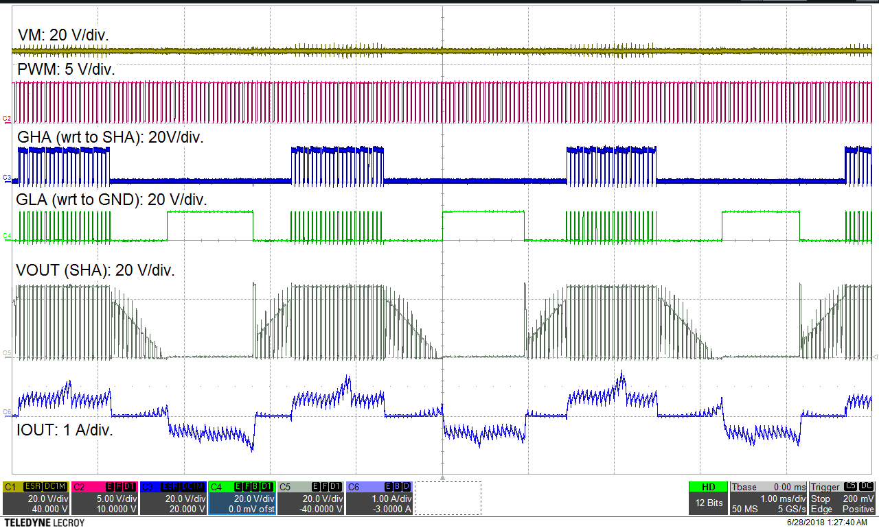 Figure 35. Motor Operation at 80% PWM Duty
 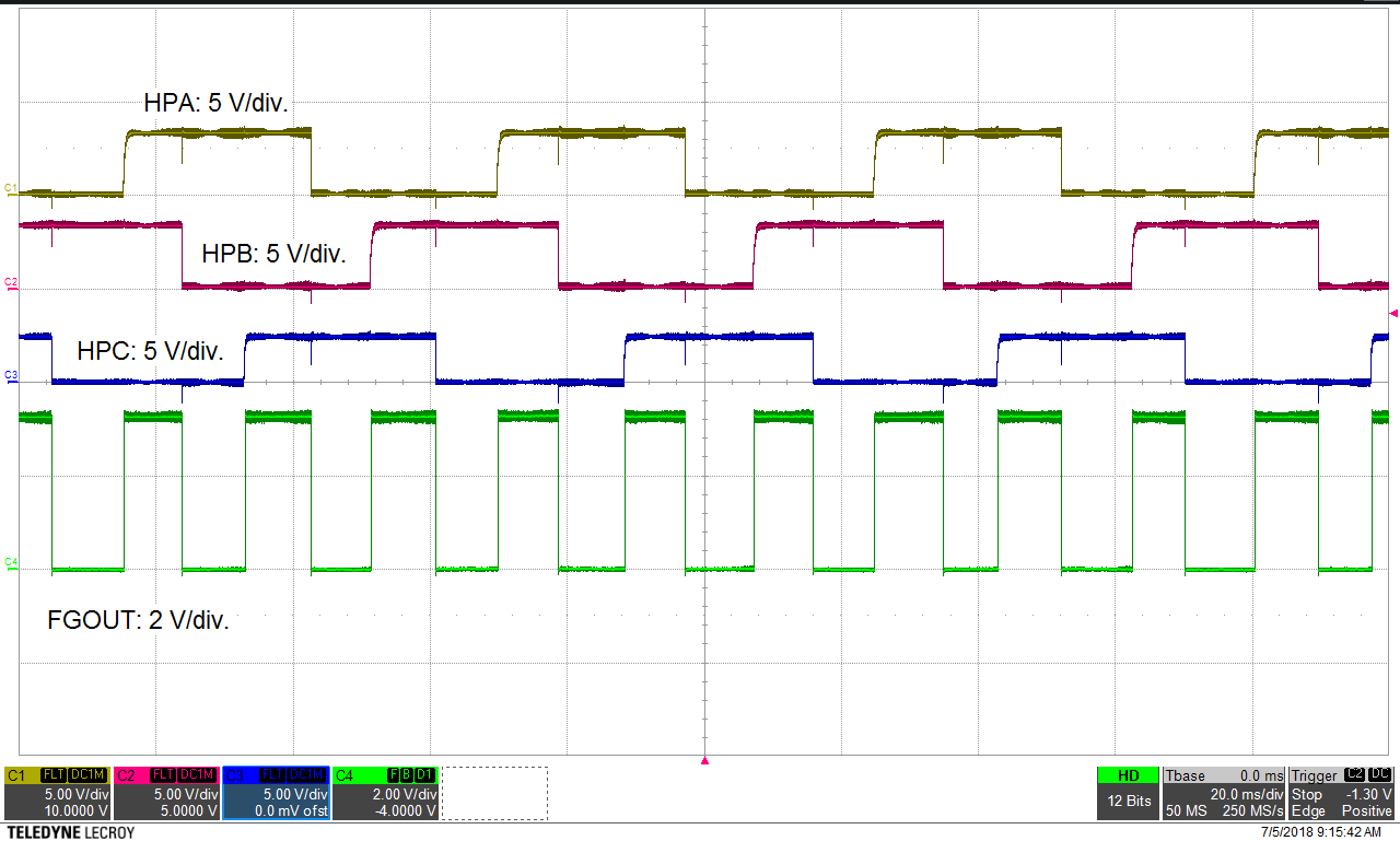 Figure 37. Hall Operation (Digital Hall Sensors Connected)
 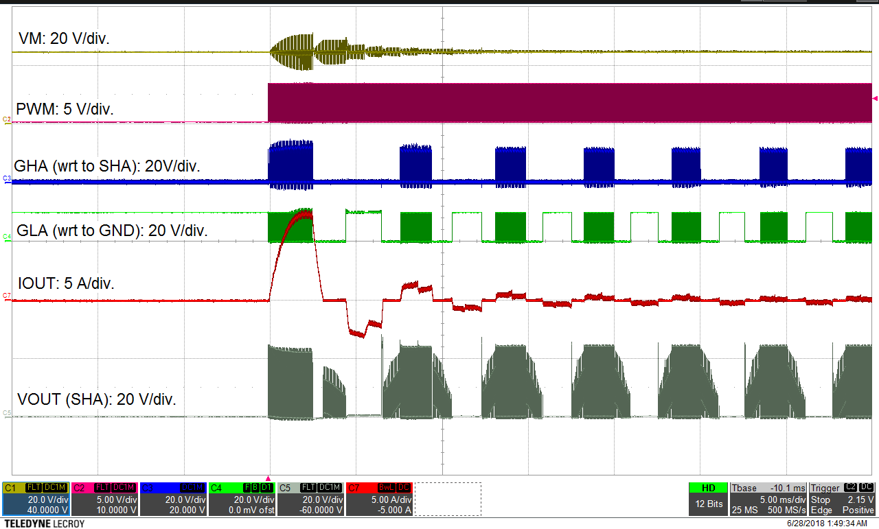 Figure 39. Motor Starting With PWM Duty Change
 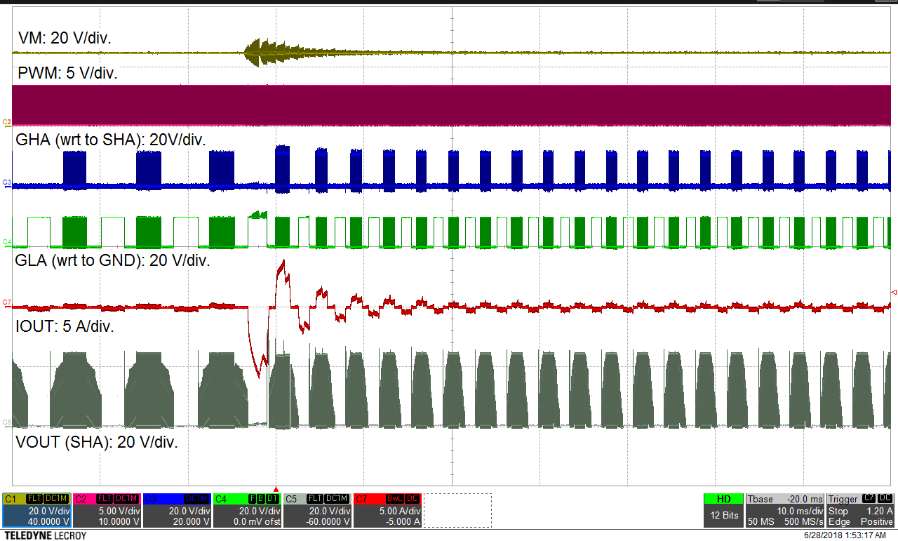 Figure 41. Motor Performance at Speed Change
  Figure 32. IDRIVE Minimum Setting
 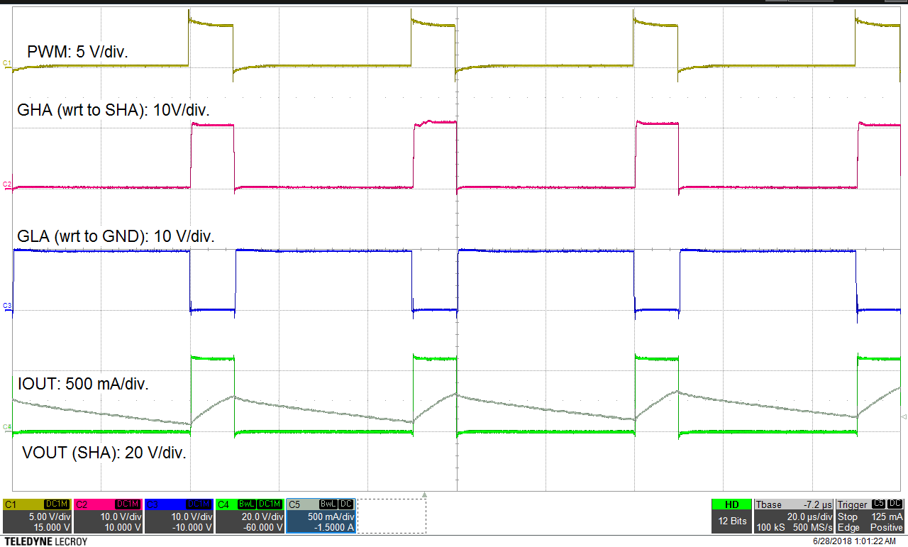 Figure 34. Gate Drive 20% Duty Cycle
 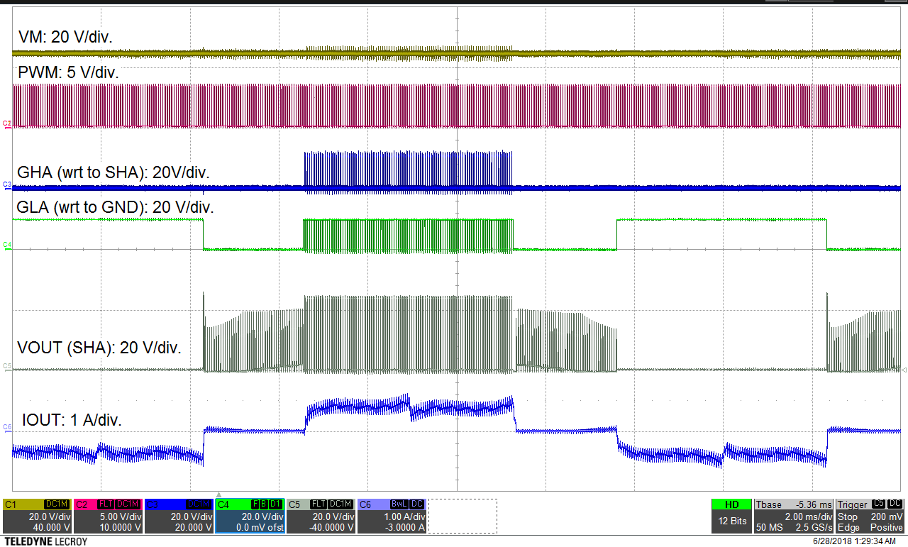 Figure 36. Motor Operation at 20% PWM Duty
 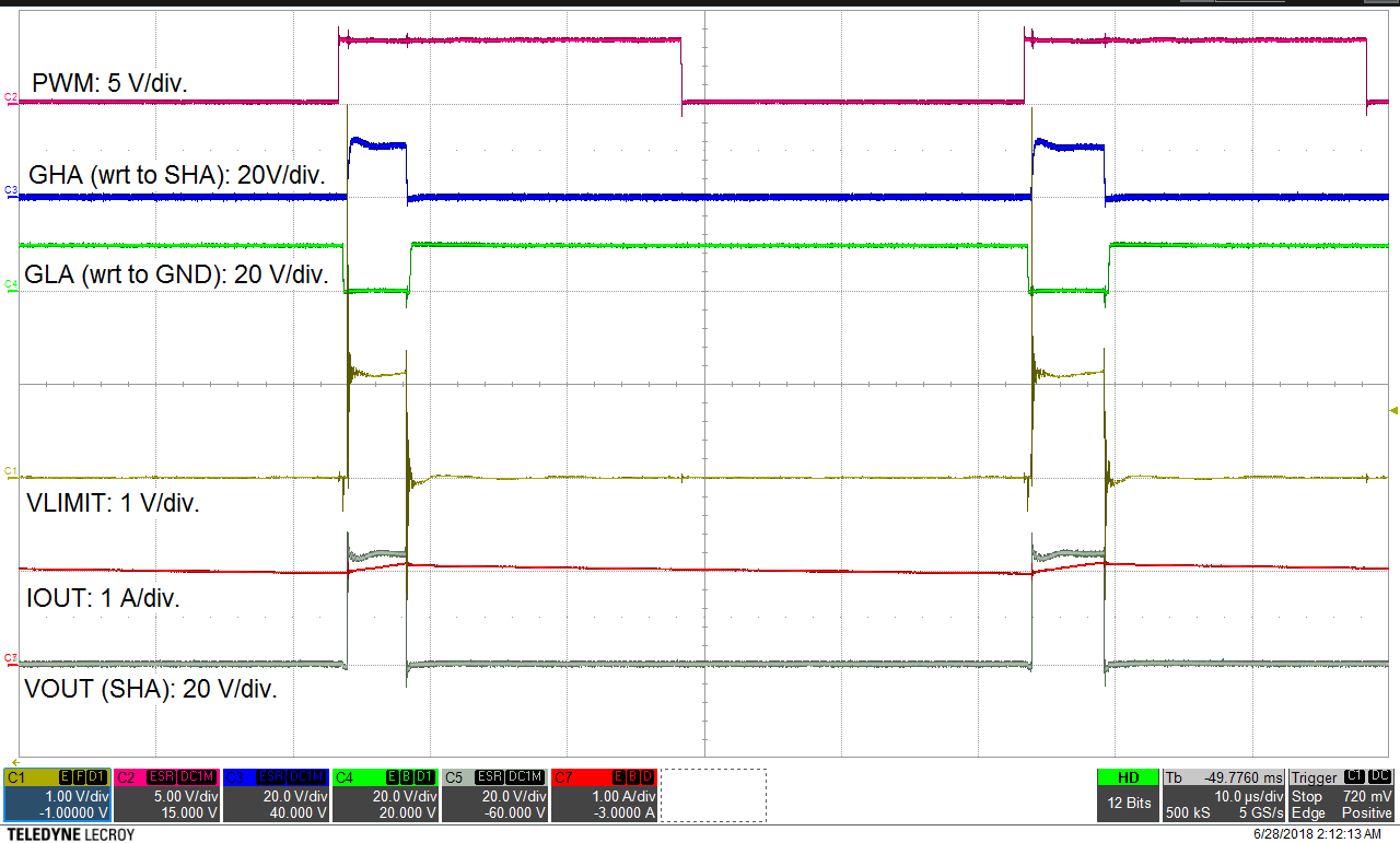 Figure 38. VLIMIT Operation
 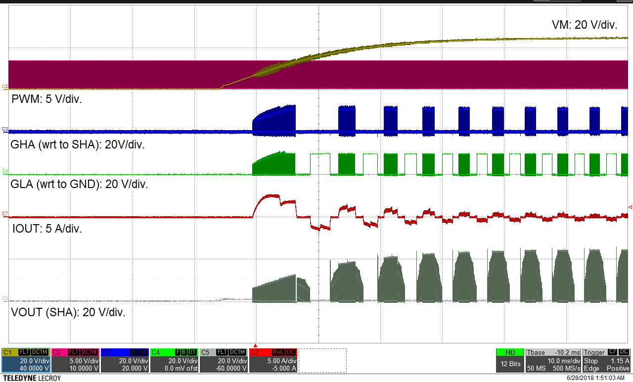 Figure 40. Motor Starting With Supply Voltage Change
 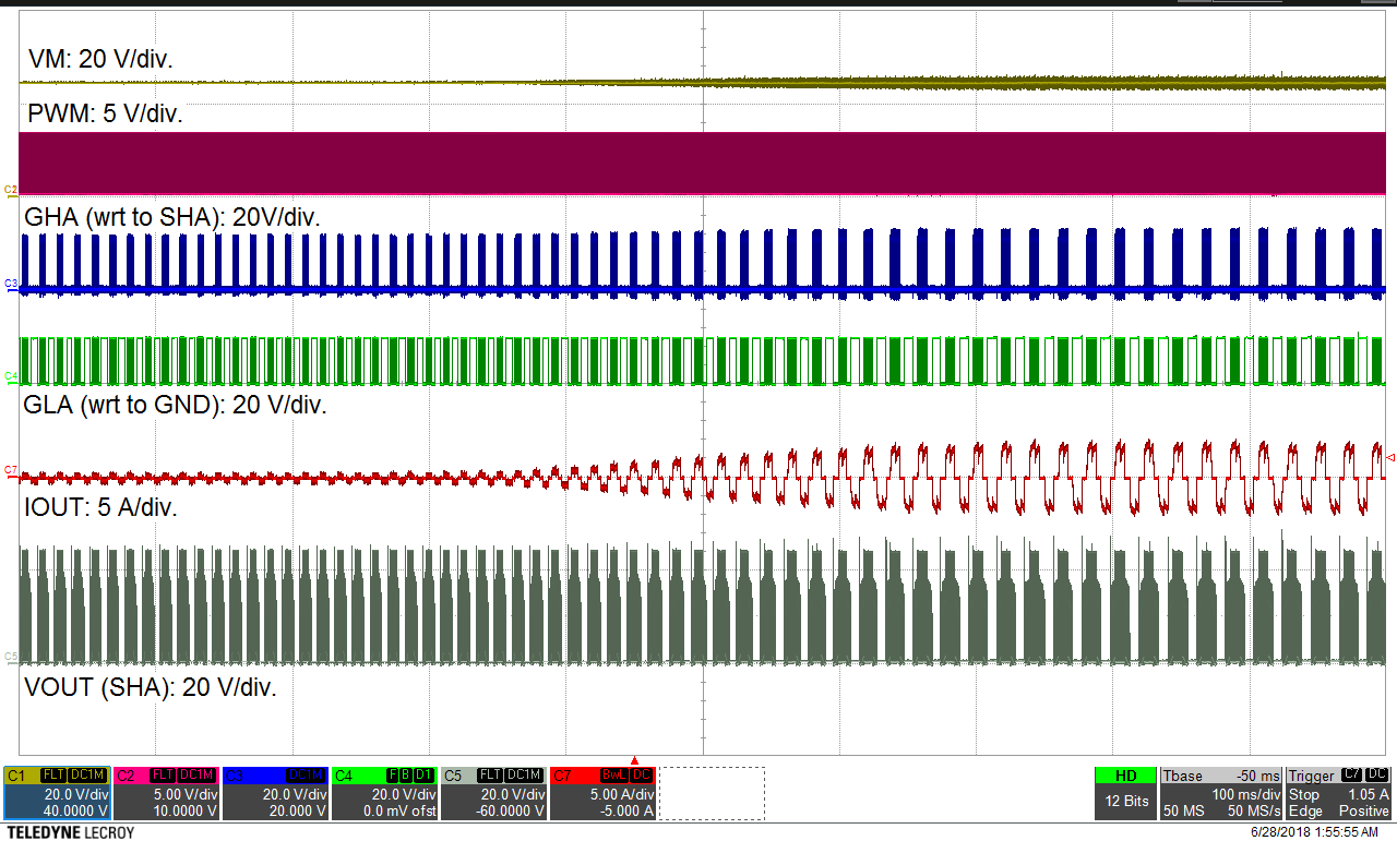 Figure 42. Motor Performance at Load Change