DLPU096A November 2019 – October 2025 DLP5534-Q1 , DLPC230-Q1 , DLPC231-Q1 , TPS99000-Q1
2.1 Kit Assembly Instructions
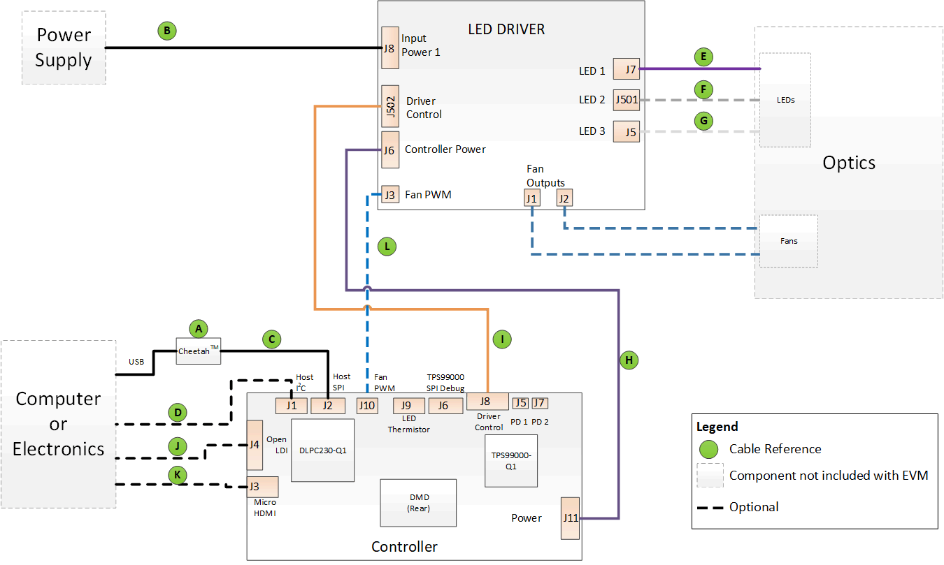
A diagram of all the EVM cable connections is shown in Figure 2-1.
- Connect the Controller to Driver control Interface flex to the Controller PCB (J8) and the Illumination Driver PCB (J502).
- Connect the Host SPI cable to the Controller PCB (J2) and the Cheetah adapter. Connect the Cheetah adapter’s USB cable to PC.
- Connect the Controller Power cable to the Controller PCB (J11) and the Illumination Driver PCB (J6).
- Connect the LED 1 Illumination output cable to the Illumination Driver PCB (J7) to the LED 1 illuminator in the optics engine.
- If there is a second illuminator connect the LED 2 Illumination output cable to the Illumination Driver PCB (J501) to the LED 2 illuminator in the optics.
- If there is a third illuminator connect the LED 3 Illumination output cable to the Illumination Driver PCB (J5) to the LED 3 illuminator in the optics engine.
- Connect the Micro HDMI cable to the Controller Board (J3). Connect the Micro HDMI cable to PC HDMI port.
- Connect the Power Input cable to the Illumination Driver Board (J8).
- If there are fans connect them to LED Driver Board (J1 and J2).
- If fan PWM is utilized then connect the Fan PWM cable from controller (J10) to LED Driver (J3).
 Figure 2-1 EVM Cable Connections