ZHCSN56C January 2021 – December 2021 TPS61094
PRODUCTION DATA
- 1 特性
- 2 應(yīng)用
- 3 說明
- 4 Revision History
- 5 Pin Configuration and Functions
- 6 Specifications
- 7 Detailed Description
- 8 Application and Implementation
- 9 Power Supply Recommendations
- 10Layout
- 11Device and Documentation Support
- 12Mechanical, Packaging, and Orderable Information
封裝選項
機械數(shù)據(jù) (封裝 | 引腳)
- DSS|12
散熱焊盤機械數(shù)據(jù) (封裝 | 引腳)
- DSS|12
訂購信息
5 Pin Configuration and Functions
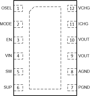
 Figure 5-1 12-Pin WSONDSS Package(Top View)
Table 5-1 Pin Functions
| PIN | I/O(1) | DESCRIPTION | |
|---|---|---|---|
| NO. | NAME | ||
| 1 | OSEL | I | Boost output voltage selection pin. Connect a resistor between this pin and ground to select one of sixteen output voltages of Boost mode. |
| 2 | MODE | I | Operation mode selection pin. The MODE pin and EN pin work together to set device operation mode. See Table 7-4. |
| 3 | EN | I | Operation mode selection pin. The MODE pin and EN pin work together to set device operation mode. See Table 7-4. |
| 4 | VIN | PWR | IC power supply input |
| 5 | SW | PWR | The switching node pin of the converter. It is connected to the drain of the internal low-side power MOSFET and the source of the internal high-side power MOSFET. |
| 6 | SUP | I | Output of buck converter to sense the voltage of the supercap |
| 7 | PGND | PWR | Power ground |
| 8 | AGND | PWR | Signal ground |
| 9, 10 | VOUT | PWR | Output of the device |
| 11 | ICHG | I | Charging current selection pin. Connect a resistor between this pin and ground to select one of sixteen output currents of Buck mode. |
| 12 | VCHG | I | Charging voltage selection pin. Connect a resistor between this pin and ground to select one of sixteen regulation voltages of Buck mode. |
(1) I = Input, PWR = Power