ZHCSI79B March 2016 – May 2018 TAS5751M
PRODUCTION DATA.
- 1 特性
- 2 應用
- 3 說明
- 4 修訂歷史記錄
- 5 Pin Configuration and Functions
-
6 Specifications
- 6.1 Absolute Maximum Ratings
- 6.2 ESD Ratings
- 6.3 Recommended Operating Conditions
- 6.4 Thermal Characteristics
- 6.5 Electrical Characteristics
- 6.6 Speaker Amplifier Characteristics
- 6.7 Protection Characteristics
- 6.8 Master Clock Characteristics
- 6.9 I²C Interface Timing Requirements
- 6.10 Serial Audio Port Timing Requirements
- 6.11 Typical Characteristics
-
7 Detailed Description
- 7.1 Overview
- 7.2 Functional Block Diagram
- 7.3 Audio Signal Processing Overview
- 7.4 Feature Description
- 7.5 Device Functional Modes
- 7.6 Programming
- 7.7
Register Maps
- 7.7.1 Register Summary
- 7.7.2
Detailed Register Descriptions
- 7.7.2.1 Clock Control Register (0x00)
- 7.7.2.2 Device ID Register (0x01)
- 7.7.2.3 Error Status Register (0x02)
- 7.7.2.4 System Control Register 1 (0x03)
- 7.7.2.5 Serial Data Interface Register (0x04)
- 7.7.2.6 System Control Register 2 (0x05)
- 7.7.2.7 Soft Mute Register (0x06)
- 7.7.2.8 Volume Registers (0x07, 0x08, 0x09)
- 7.7.2.9 Volume Configuration Register (0x0E)
- 7.7.2.10 Modulation Limit Register (0x10)
- 7.7.2.11 Interchannel Delay Registers (0x11, 0x12, 0x13, and 0x14)
- 7.7.2.12 PWM Shutdown Group Register (0x19)
- 7.7.2.13 Start/Stop Period Register (0x1A)
- 7.7.2.14 Oscillator Trim Register (0x1B)
- 7.7.2.15 BKND_ERR Register (0x1C)
- 7.7.2.16 Input Multiplexer Register (0x20)
- 7.7.2.17 PWM Output MUX Register (0x25)
- 7.7.2.18 AGL Control Register (0x46)
- 7.7.2.19 PWM Switching Rate Control Register (0x4F)
- 7.7.2.20 Bank Switch and EQ Control (0x50)
-
8 Application and Implementation
- 8.1 Application Information
- 8.2
Typical Applications
- 8.2.1
Stereo Bridge Tied Load Application
- 8.2.1.1 Design Requirements
- 8.2.1.2 Detailed Design Procedure
- 8.2.1.3 Application Performance Plots
- 8.2.2 Mono Parallel Bridge Tied Load Application
- 8.2.1
Stereo Bridge Tied Load Application
- 9 Power Supply Recommendations
- 10Layout
- 11器件和文檔支持
- 12機械、封裝和可訂購信息
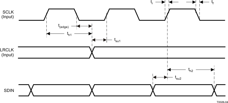
6.10 Serial Audio Port Timing Requirements
over recommended operating conditions (unless otherwise noted)| PARAMETER | TEST CONDITIONS | MIN | TYP | MAX | UNIT | |
|---|---|---|---|---|---|---|
| fSCLKIN | Frequency, SCLK 32 × fS, 48 × fS, 64 × fS | CL ≤ 30 pF | 1.024 | 12.288 | MHz | |
| tsu1 | Setup time, LRCK to SCLK rising edge | 10 | ns | |||
| th1 | Hold time, LRCK from SCLK rising edge | 10 | ns | |||
| tsu2 | Setup time, SDIN to SCLK rising edge | 10 | ns | |||
| th2 | Hold time, SDIN from SCLK rising edge | 10 | ns | |||
| LRCK frequency | 8 | 48 | 48 | kHz | ||
| SCLK duty cycle | 40% | 50% | 60% | |||
| LRCK duty cycle | 40% | 50% | 60% | |||
| SCLK rising edges between LRCK rising edges | 32 | 64 | SCLK edges | |||
| t(edge) | LRCK clock edge with respect to the falling edge of SCLK | –1/4 | 1/4 | SCLK period | ||
| tr/tf | Rise/fall time for SCLK/LRCK | 8 | ns | |||
| LRCK allowable drift before LRCK reset | 4 | MCLKs | ||||

NOTE:
On power up, hold the TAS5751M RST LOW for at least 100 μs after DVDD has reached 3 V.NOTE:
If RST is asserted LOW while PDN is LOW, then RST must continue to be held LOW for at least 100 μs after PDN is deasserted (HIGH). Figure 2. SCL and SDA Timing
  Figure 3. Start and Stop Conditions Timing
  Figure 4. Serial Audio Port Timing