SLVAF13 November 2020 LM5069 , TPS1663 , TPS2663
3.3 Performance Results
Figure 3-1 shows the PCB with four TPS26631 devices.
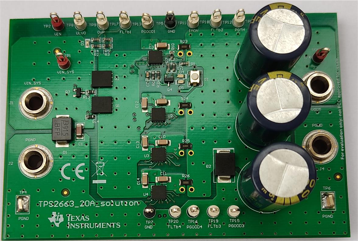 Figure 3-1 Evaluation Board With Four
TPS26631 Devices in Parallel
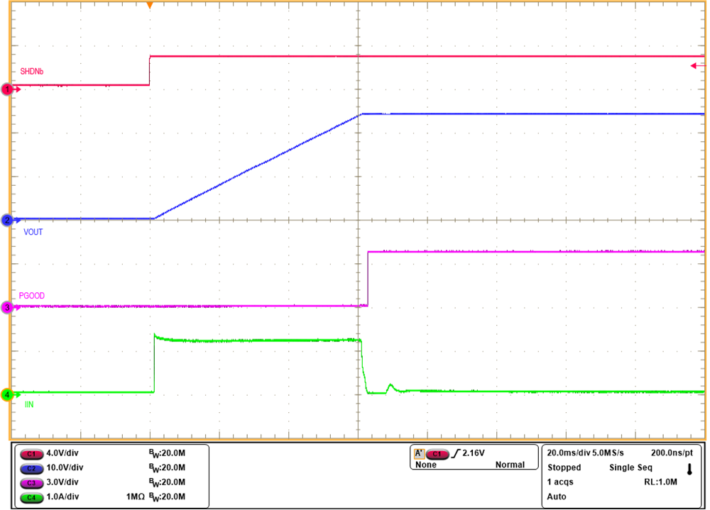 Figure 3-2 Turn-on Control With
SHDN
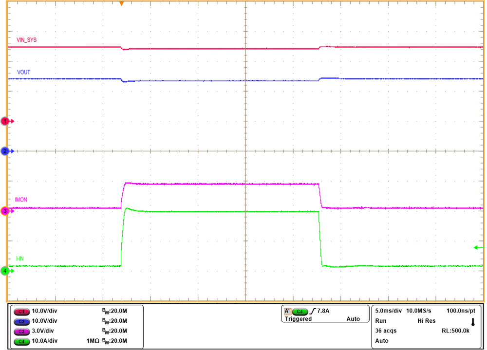 Figure 3-4 IMON Response During Load
Current Step From 2 A to 20 A
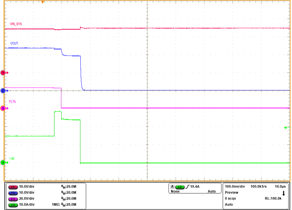 Figure 3-6 Overload Performance
During Load Current Step From 15 A to 28 A
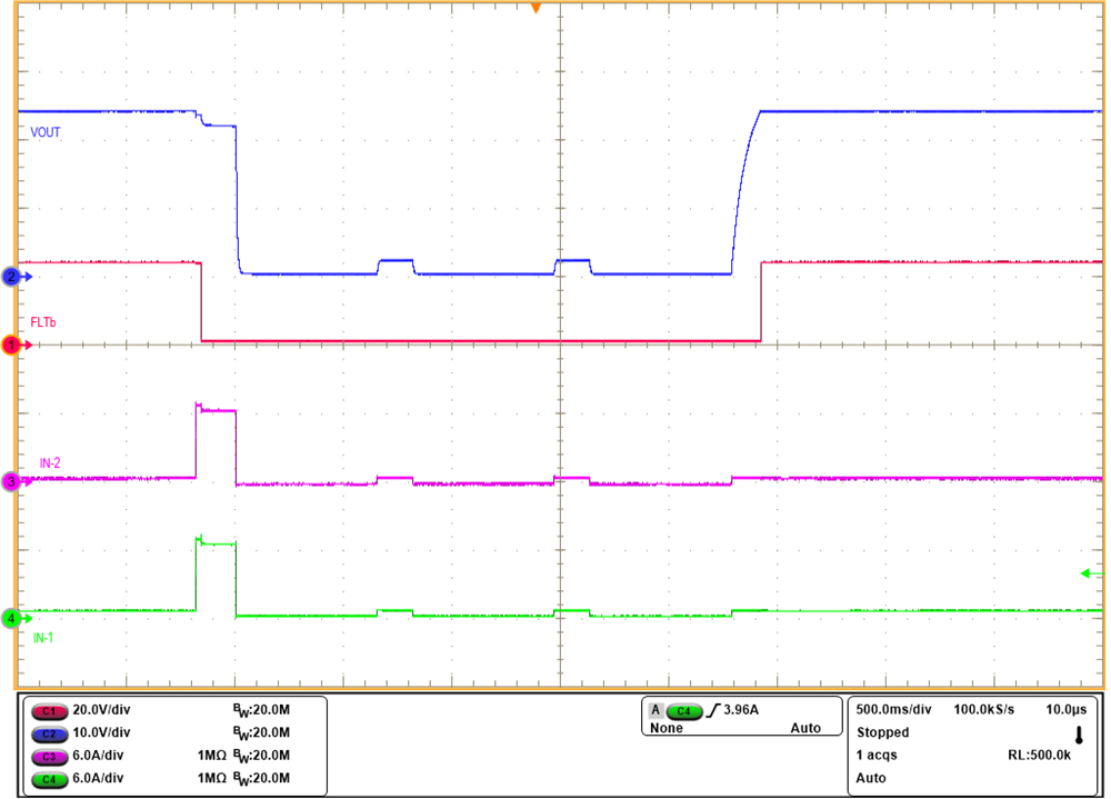 Figure 3-8 Response During Recovery
From Overload Fault
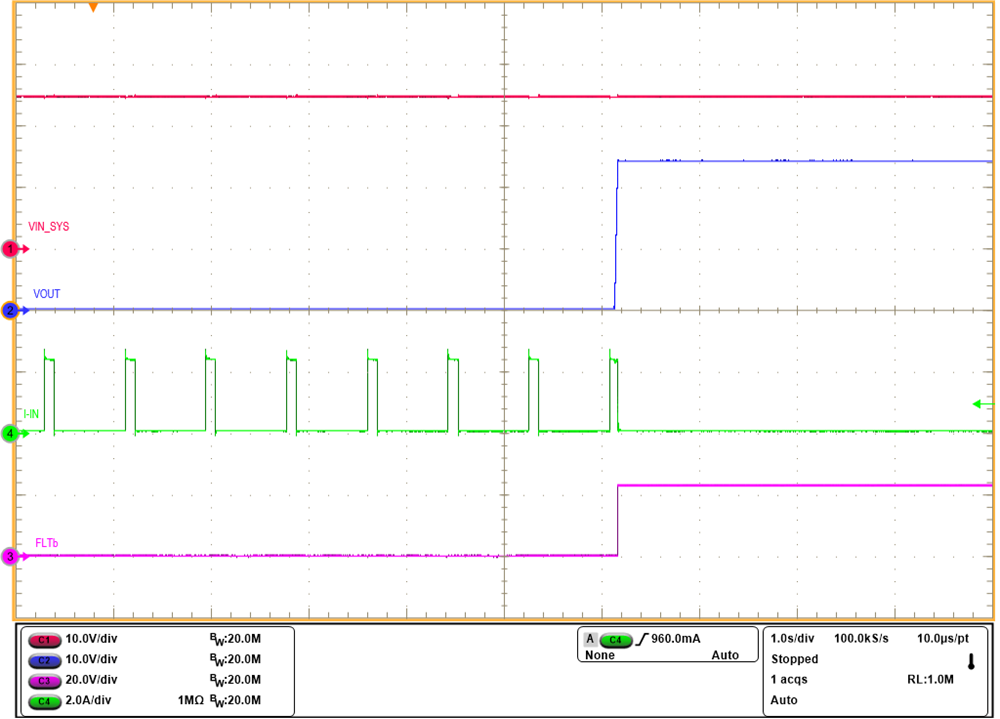 Figure 3-10 Response During Recovery
From Output Short-Circuit
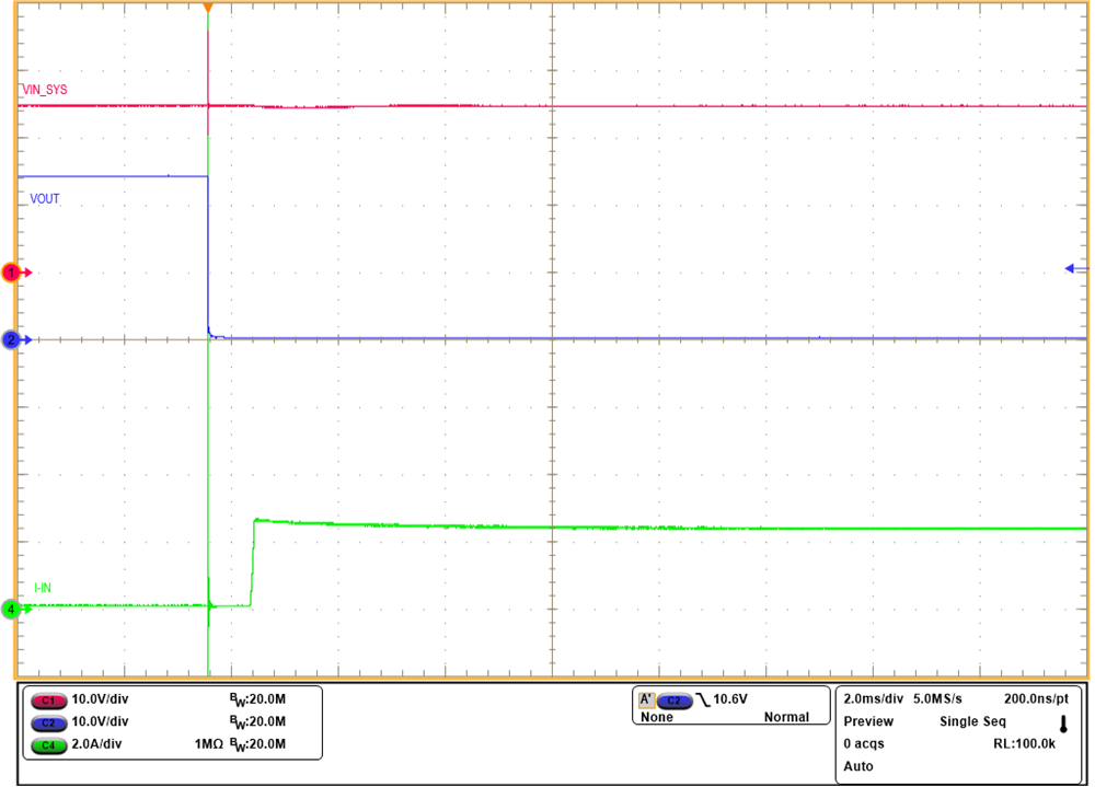 Figure 3-12 Response During Hot-Short
at the Output
Figure 3-12 Response During Hot-Short
at the OutputFigure 3-14 Voltage Interruption
Response of Four TPS26630 Devices in Parallel Configuration (POUT
= 45 W; COUT = 3 mF)
Figure 3-16 –500-V, 2-Ω Surge Response
of Four TPS26631 Devices in Parallel Configuration
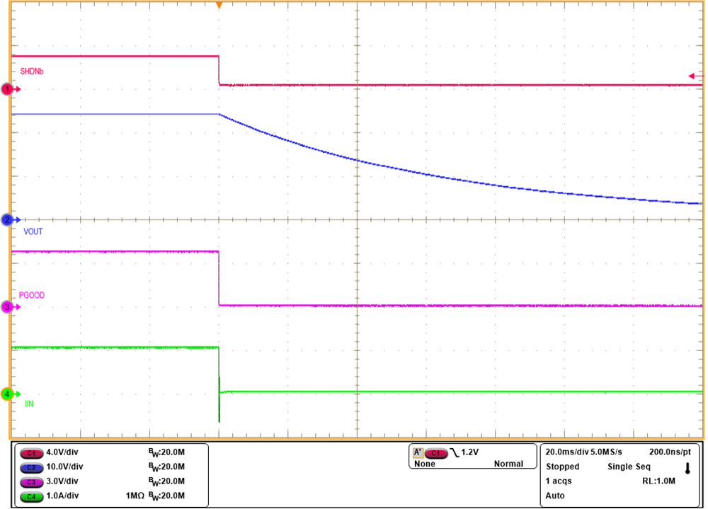 Figure 3-3 Turn-off Control With
SHDN
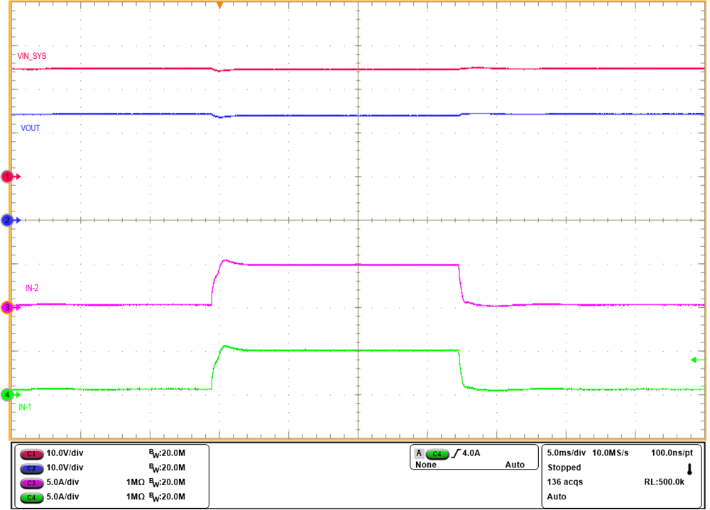 Figure 3-5 Current Sharing Between
Two Devices During Load Current Step from 2 A to 20 A
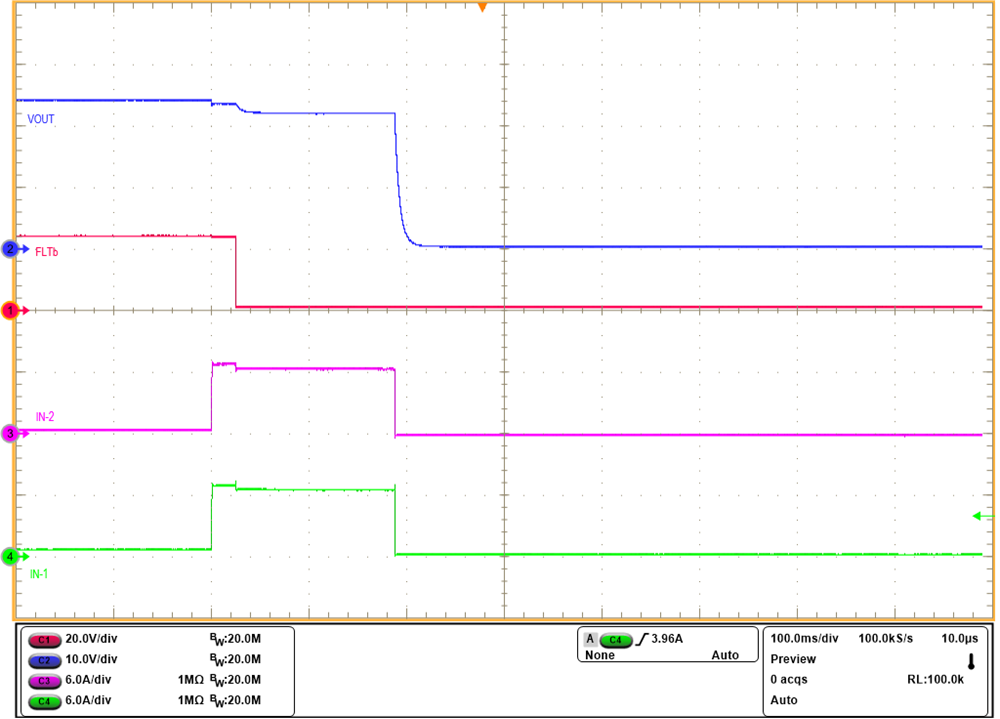 Figure 3-7 Current Sharing Between
Two Devices During Overload Fault
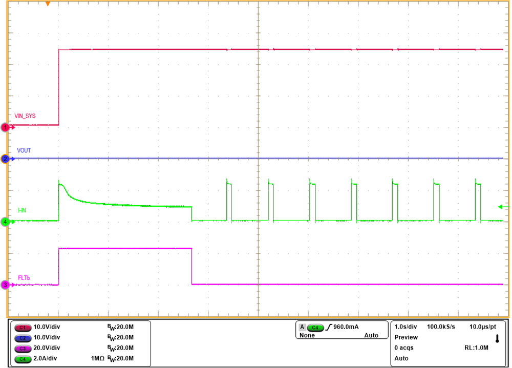 Figure 3-9 Response During Start-up
With Short on Output
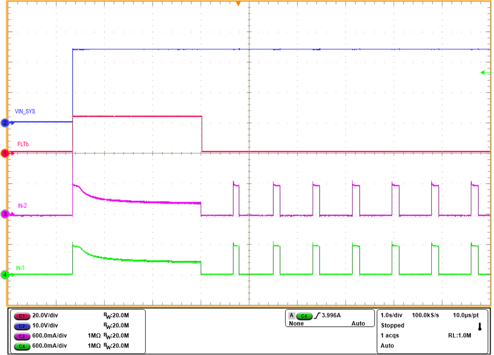 Figure 3-11 Current Sharing Between
Two Devices During Start-up With Short on Output
Figure 3-11 Current Sharing Between
Two Devices During Start-up With Short on OutputFigure 3-13 Mismatch (%) in
Steady-State Current Sharing in a Four eFuse Parallel Configuration
Figure 3-15 500-V, 2-Ω Surge Response
of Four TPS26631 Devices in Parallel Configuration