SBOA442 March 2021 TMP107 , TMP107-Q1
5 Test Setup
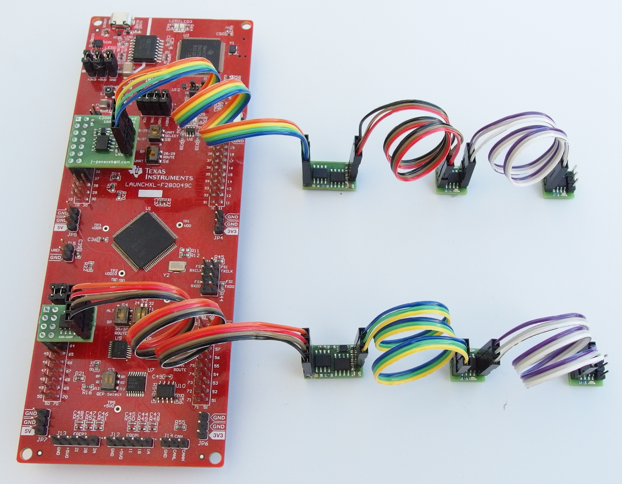
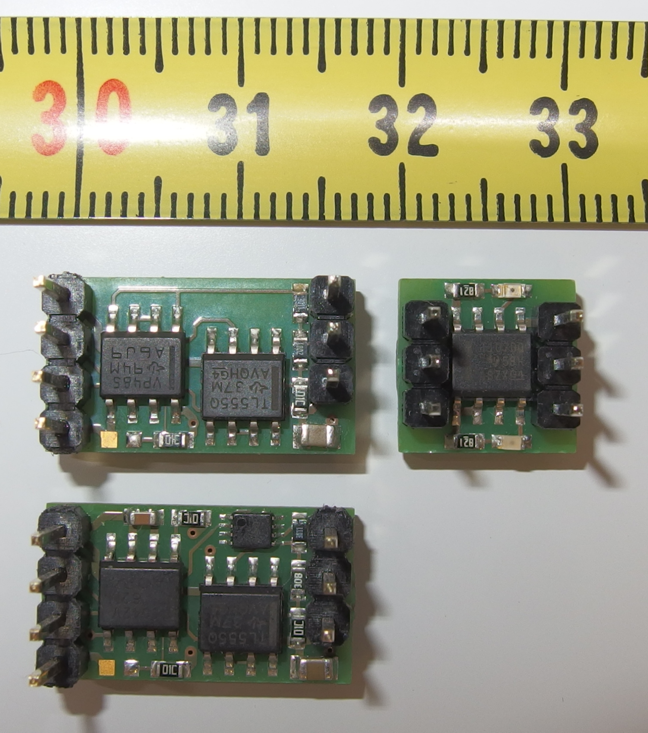
The test setup consists of the LAUNCHXL-F280049C development board and custom PCB boards. Figure 5-1 and Figure 5-2 show the actual circuit diagrams for boards under test. Figure 5-3 shows the test setup. Small adapter boards plugged directly to the C2000? MCU LaunchPad? convert UART interface to CAN or RS-485. Small converters in the middle translate the signal to SMAART wire bus interface compatible. Printed circuit boards on the right host individual TMP107-Q1 temperature sensors.
 Figure 5-1 Circuit Diagram of the CAN
to SMAART wire? Interface Converter
 Figure 5-2 Circuit Diagram of the
RS-485 to SMAART wire? Interface
Converter
 Figure 5-3 Test Setup
 Figure 5-4 Detail of the Converter
Boards and the Temperature Sensor Board
Figure 5-4 Detail of the Converter
Boards and the Temperature Sensor BoardNote: Contact TI on the www.ti.com/e2e support forum for further information on the demo
firmware for the C2000? microcontroller and design data in KiCad
format.