DLPU097A November 2019 – October 2025 DLP5534-Q1 , DLPC230-Q1 , DLPC231-Q1 , TPS99000-Q1
1.1.1 Controller PCB
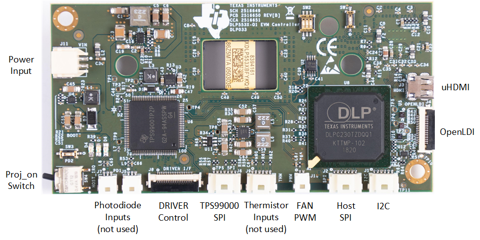
The Controller PCB shown in Figure 1-2 includes the DLP5534-Q1 DMD, the DLPC230-Q1 DMD Controller, and the TPS99000-Q1. It supports video inputs from either a micro HDMI or OpenLDI interface and provides the formatting and control to display the video on the DLP5534-Q1 DMD. The EVM can be controlled with either an SPI or I2C interface. The SPI or I2C interface can also be used to reprogram the serial Flash that is used to store DLPC230-Q1 software and configuration. An optional second SPI port is provided for monitoring the TPS99000-Q1. The EVM includes a flex interface to control the Illumination Driver PCB. The EVM has external photodiode inputs and thermistor inputs which are not used for this application.
 Figure 1-2 EVM Controller PCB
The Controller PCB contains the ports listed in Table 1-1. Indicator LEDs are listed in Table 1-2.
| SCHEMATIC REFERENCE | FUNCTION |
|---|---|
| J1 | Host I2C, PROJ_ON, HOLD_BOOT, HOST_IRQ |
| J2 | Host SPI |
| J3 | Micro HDMI |
| J4 | OpenLDI (Flex connector) |
| J5 | Photodiode 1(1) |
| J6 | TPS99000-Q1 SPI Debug |
| J7 | Photodiode 2(1) |
| J8 | LED Driver Interface |
| J9 | LED Thermistor(1) |
| J10 | Fan PWM output (optional) |
| J11 | Controller Power |
| SCHEMATIC REFERENCE | FUNCTION |
|---|---|
| D4 (Green) | Input power to Controller (from Illumination Driver) Off: No power connected On: Power connected |
| D5 (Green) | PROJ_ON Off: System Off On: System On |
| D6 (Red) | HOST_IRQ Off: Interrupt not asserted On: Interrupt asserted |
The Controller PCB switches are listed in Table 1-3. SW4 is a toggle switch for PROJ_ON which is used to turn on and off the electronics. Note that parts of the board are still powered when PROJ_ON is in the off position. SW1, SW2, and SW3 are dip switches that control the states of configuration signals the DLPC230-Q1 reads when it comes out of reset. These switches should be set based on the desired configuration options.
| SCHEMATIC REFERENCE / SIGNAL NUMBER | FUNCTION |
|---|---|
| SW1 (1) | Spread Spectrum Enable Off: Disabled On: Enabled |
| SW2 (1) | Host Port Checksum Select Off: CRC On: Checksum |
| SW2 (2) | Host Interface Select Off: Host SPI On: Host I2C |
| SW2 (3) | Host SPI Mode Off: Mode 0 or 3 On: Mode 1 or 2 |
| SW3 | Hold in Boot Off: Do not hold in boot (continue to main application) On: Hold in boot |
| SW4 | PROJ_ON Off: Turn off system On: Turn on system On state is toward the closest corner of the board Figure 1-2 |