ZHCSKN9B December 2019 – December 2022 LMR36506
PRODUCTION DATA
- 1 特性
- 2 應用
- 3 說明
- 4 Revision History
- 5 Device Comparison Table
- 6 Pin Configuration and Functions
- 7 Specifications
-
8 Detailed Description
- 8.1 Overview
- 8.2 Functional Block Diagram
- 8.3
Feature Description
- 8.3.1 Enable, Start-up, and Shutdown
- 8.3.2 Adjustable Switching Frequency (with RT)
- 8.3.3 Power-Good Output Operation
- 8.3.4 Internal LDO, VCC UVLO, and VOUT/BIAS Input
- 8.3.5 Bootstrap Voltage and VCBOOT-UVLO (CBOOT Terminal)
- 8.3.6 Output Voltage Selection
- 8.3.7 Soft Start and Recovery from Dropout
- 8.3.8 Current Limit and Short Circuit
- 8.3.9 Thermal Shutdown
- 8.3.10 Input Supply Current
- 8.4 Device Functional Modes
-
9 Application and Implementation
- 9.1 Application Information
- 9.2
Typical Application
- 9.2.1 Design Requirements
- 9.2.2 Detailed Design Procedure
- 9.2.3 Application Curves
- 9.3 Best Design Practices
- 9.4 Power Supply Recommendations
- 9.5 Layout
- 10Device and Documentation Support
- 11Mechanical, Packaging, and Orderable Information
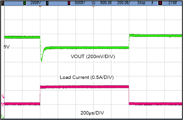
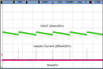
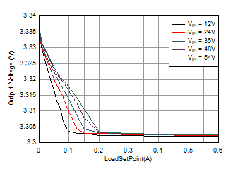
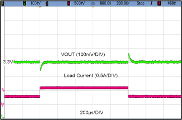
9.2.3 Application Curves
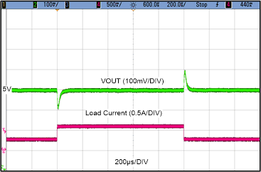
Unless otherwise specified the following conditions apply: VIN = 24V, TA
= 25°C.
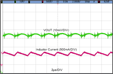
Unless otherwise specified the following conditions apply: VIN = 24V, TA
= 25°C.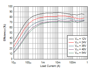
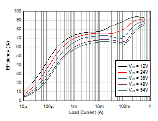
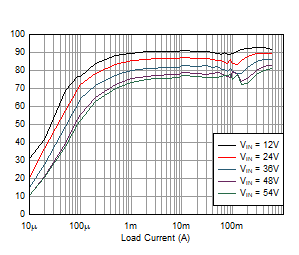
Figure 9-4 Efficiency. Unless otherwise specified the following conditions apply: VIN = 24V, TA
= 25°C.

| LMR36506R3 | VOUT = 3.3 V Fixed | 1 MHz (AUTO) |
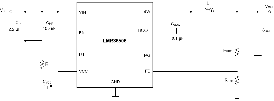 Figure 9-18 Schematic for Typical
Application Curves
Figure 9-18 Schematic for Typical
Application CurvesTable 9-3 BOM for Typical Application
Curves
| U1 | ?SW | VOUT | L | NOMINAL COUT
(RATED CAPACITANCE) |
RT pin | RFBT | RFBB |
|---|---|---|---|---|---|---|---|
| LMR36506R3RPER | 1000 kHz | 3.3 V (Fixed) | 15 μH, 260 mΩ | 2 × 22 μF | Short to VCC | 0 Ω | Open |
| LMR36506RRPER | 400 kHz | 5 V | 47 μH, 68.4 mΩ | 2× 22 μF | 39.2 kΩ | 100 kΩ | 24.9 kΩ |
| LMR36506R5RPER | 1000 kHz | 5 V (Fixed) | 22 μH, 99.65 mΩ | 2 x 22 μF | Short to VCC | 0 Ω | Open |
