ZHCSHN8B February 2018 – October 2018 LMG1020
PRODUCTION DATA.
10.2 Layout Example
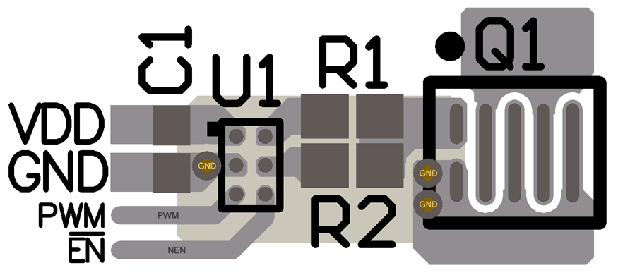
Figure 15 presents a typical layout of LMG1020 with a 0402 decoupling capacitor C1, which is placed as close as possible to LMG1020. The ground return at GaN FET Kelvin source immediately flows through a via to the closest inner layer, and overlaps with the top layer traces.
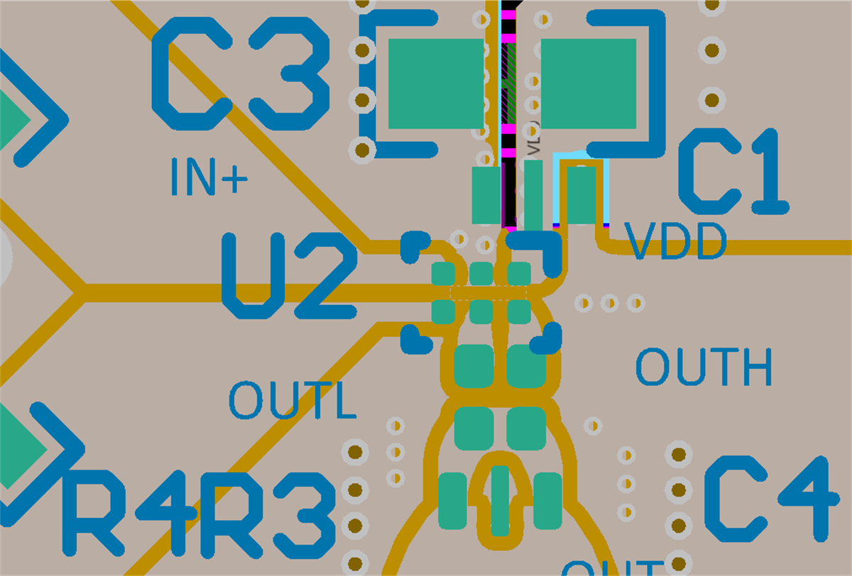
Figure 16 presents a layout of LMG1020 with a 0.1 µF feed-through capacitor (C1) and a larger 1uF capacitor (C3) for decoupling. In this design, the feed-through capacitor C1 is placed in a shunt-through manner for lower noise decoupling, and C3 is placed next to C1. 0201 resistors are used at the output of LMG1020, which brings lower parasitic inductance than 0402 package.
 Figure 15. Typical LMG1020 Layout With Ball-Grid GaN FET And 0402 Decoupling Capacitor
  Figure 16. Typical Layout Of LMG1020 And A Feed-Through Decoupling Capacitor With A Capacitor Load