SSZTCR4 may 2015 LDC1312 , LDC1314 , LDC1612 , LDC1614
Last week, I introduced the latest addition to our inductance-to-digital converter (LDC) portfolio. We released four multichannel LDCs: the LDC1312 and LDC1612, which feature two matched channels; and the LDC1314 and LDC1614, which have four matched channels. In this post, the first in a series, I will explain how to configure them in a multichannel system.
Benefits
There are several benefits to multichannel designs:
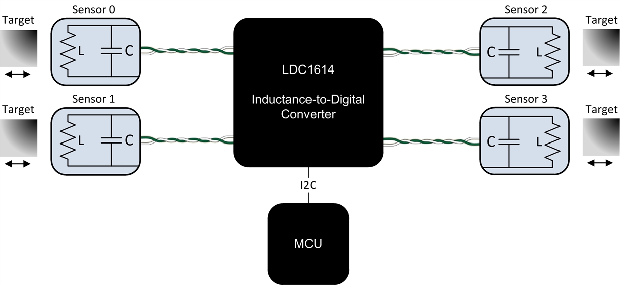
- Systems that require multiple sensors can now use a single IC, as shown in Figure 1. This results in a lower system cost and greatly simplifies system design because sensors can be placed remotely from the LDC.
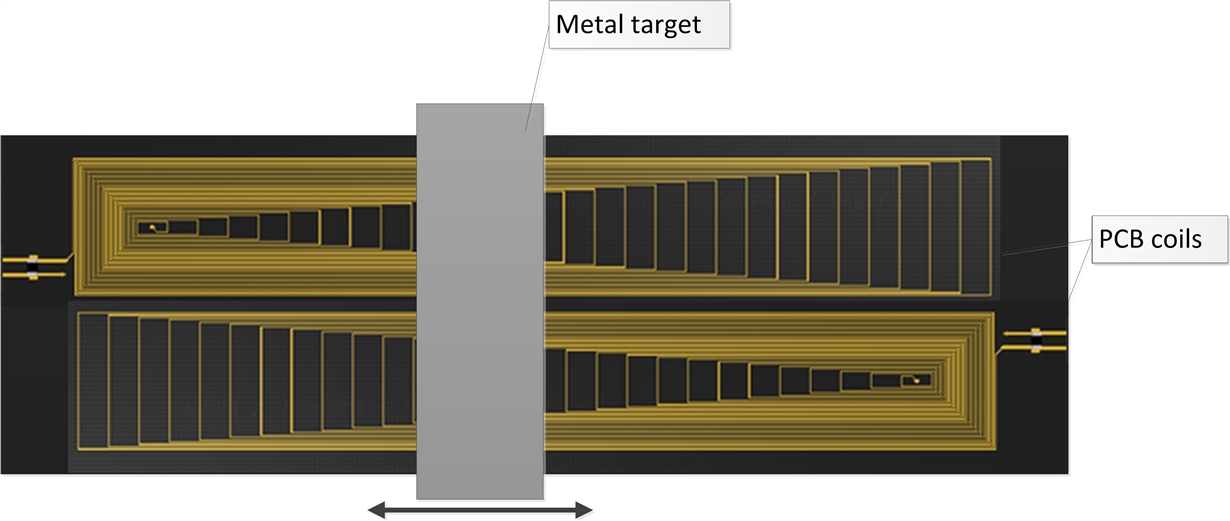
- The individual channels are well matched in terms of parasitics and sensor drive. These well-matched channels can be used for high-precision differential designs, such as the differential linear position sensing shown in Figure 2. Alternatively, one channel can be used as a reference coil that has no target, or a target at a fixed position. The reference-coil channel can be used to set a threshold, compensate for temperature variation, or determine target distance in a lateral or rotational position-sensing system.
- The reduced system overhead of a multichannel architecture also reduces power consumption.
 Figure 1 The New Multichannel Core Simplifies Systems with Multiple Sensors
 Figure 2 A Multichannel Core Improves Performance in High-precision Differential Designs
Channel Selection
The LDC has two modes of operation:
- Single-channel (continuous) mode: In this mode, the LDC activates the connected sensor and then continuously converts on the selected channel. To put the device into this mode, you would set the following registers:
- Put the LDC into single-channel mode by setting AUTOSCAN_EN = 0 (register 0x1B, bit [15]). Note that setting this mode results in RR_SEQUENCE (register 0x1B, bit [14:13]) having no effect.
- ACTIVE_CHAN (register 0x1A, bit [15:14]) selects the active channel. Set this value to the desired channel (e.g., 00 will select channel 0).
Keep in mind that the high-current sensor-drive feature (HIGH_CURRENT_DRV, register 0x1A: bit [6]) is only available in single-channel mode for channel 0.
- Multichannel (sequential) mode: In this mode, the LDC switches between the selected channels in a round-robin fashion. To configure the device in this mode, set the following registers:
- AUTOSCAN_EN = 1 (register 0x1B, bit [15]) to set multichannel mode. When this is set, ACTIVE_CHAN (register 0x1A, bit [15:14]) has no effect.
- RR_SEQUENCE = 00 (register 0x1B, bit [14:13]) selects conversion on channels 0 and 1. On the four-channel LDC1314 and LDC1614, option 01 enables three channels (channels 0-2) and option 10 enables all four channels (channels 0-3).
The multichannel devices include an internal filter to reduce the sensitivity to sensor noise. Set the DEGLITCH setting (register 0x1B, bit [2:0]) appropriately. This setting is common for all selected channels. In some applications, different sensor designs may be used for different channels. Therefore, it is important to choose the lowest DEGLITCH bandwidth setting that is still above the highest-frequency channel.
In this first installment, I’ve explained how to configure LDCs in multichannel mode. If you are using the LDC1312, LDC1314, LDC1612 or LDC1614 in a multichannel system, be sure to check out the next installment in this series, when I’ll explain the timing of these multichannel systems.
Additional Resources
- Learn more about inductive sensing.
- Watch a video to learn how to design a 16-button keypad with TI’s inductive sensing technology.
- Read other blog posts about designing with LDCs.
- Start a multichannel design with WEBENCH? Inductive Sensing Designer.