SSZTCB1 August 2015 LDC1312 , LDC1314 , LDC1612 , LDC1614
Designing coils for inductive sensing may initially appear like a daunting task, but the WEBENCH? Coil Designer makes the process very simple.
If you have designed with TI's inductance-to-digital converters (LDCs), then you may have already used WEBENCH Designer for Inductive Sensing Applications, which suggests suitable coils for given input parameters and exports them to PCB CAD tools.
Figure 1 is a screenshot of our second inductive sensing WEBENCH tool. WEBENCH Coil Designer designs custom sensor coils for applications where you already know the system constraints. It supports real-world PCB manufacturing constraints such as adjustment of trace geometries and PCB thickness.
Both tools export the resulting coil directly to popular PCB layout tools and allow complete sensor coil design in only five minutes.
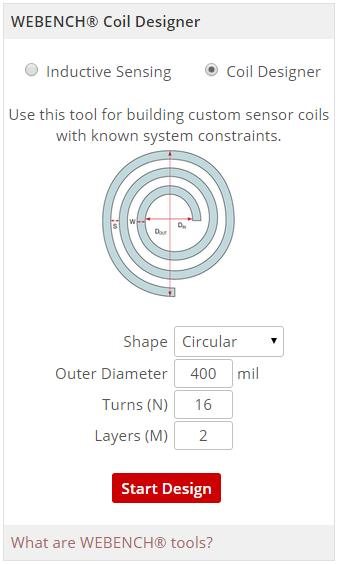 Figure 1 WEBENCH Offers Two Tools for
Inductive Sensing
Figure 1 WEBENCH Offers Two Tools for
Inductive SensingYou can design a custom sensor coil in five simple steps:
1. Select LDC Device:
Let’s use the LDC1612 to design a coil. While this selection does not impact the coil directly, we recommend selecting the most appropriate LDC because WEBENCH Coil Designer considers device-specific boundary conditions during its calculations (Figure 2).
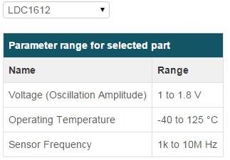 Figure 2 WEBENCH Coil Designer Displays
and Considers Device-specific Boundary Conditions
Figure 2 WEBENCH Coil Designer Displays
and Considers Device-specific Boundary Conditions2. Select Coil Type:
WEBENCH Coil Designer supports four coil types. Circular coils are used for most applications because they offer a higher Q-factor than the other choices, but sometimes system geometry requirements and sensor inductance requirements dictate the use of square coils. Figure 3 defines inner and outer coil diameter, trace width and trace spacing.
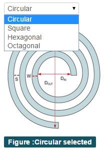 Figure 3 WEBENCH Coil Designer Supports
Circular, Hexagonal, Octagonal and Square Coil
Figure 3 WEBENCH Coil Designer Supports
Circular, Hexagonal, Octagonal and Square Coil3. Select Coil Geometry and Other Parameters:
In this window, I specified the physical coil properties such as the number of turns, PCB layers and trace geometries, as shown in Figure 4.
Trace width and trace spacing affect the manufacturing cost; narrower traces and spacing typically result in more expensive PCBs. The outer coil diameter has the largest impact on the maximum sensing range. A coil fill ratio (inner diameter / outer diameter) of ≥ 0.3 is recommended. Typically, smaller coil fill ratios do not improve performance because the innermost turns add little inductance compared to the increase in AC resistance, and therefore have a reduced Q-factor. The “view more” option shows advanced information about the sensor.
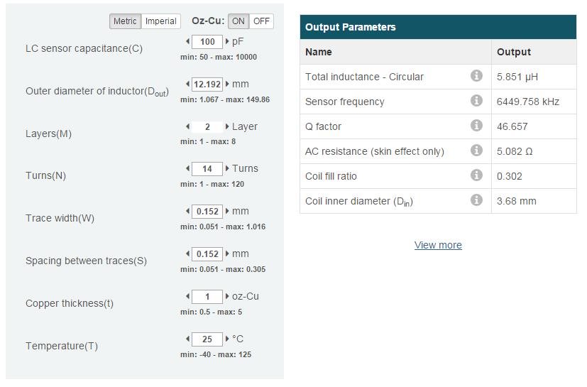 Figure 4 Output Parameters for Given
Coil Geometries. Clicking ‘View More’ Displays Advanced Output
Parameters
Figure 4 Output Parameters for Given
Coil Geometries. Clicking ‘View More’ Displays Advanced Output
ParametersThe WEBENCH tool displays a warning if violations of device-specific boundary conditions or recommendations occur. For example, a sensor with an oscillation frequency of 8MHz is suitable for the LDC1612, but not for the LDC1000, which has a maximum sensor frequency of 5MHz (Figure 5).
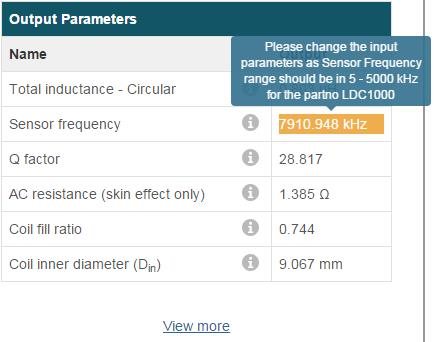 Figure 5 Designing an 8MHz Sensor for
the LDC1000 Produces a Warning and Recommendation for Avoiding the
System Constraint
Figure 5 Designing an 8MHz Sensor for
the LDC1000 Produces a Warning and Recommendation for Avoiding the
System Constraint4. Output Graph:
The window in Figure 6 shows the sensor characteristics based on the inputs in step 3. The tool generates a wide range of plots after you select the desired parameters from the drop-down menus, and compares the performance of different coil types.
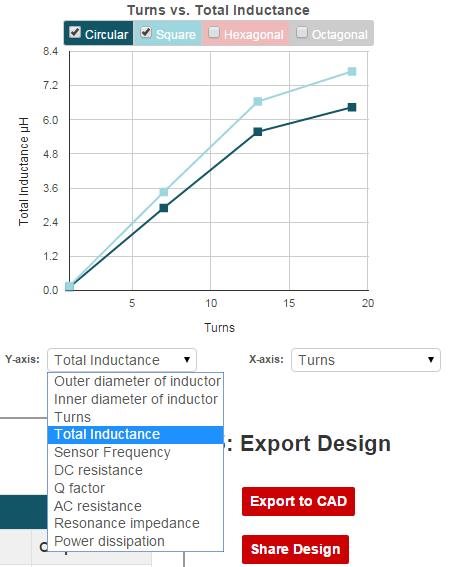 Figure 6 Output Parameters Plotted
against Input Parameters and Compared to Different Coil Types
Figure 6 Output Parameters Plotted
against Input Parameters and Compared to Different Coil Types5. Export Design:
Finally, you can export the coil design into one of five different PCB CAD tools, as shown in Figure 7.
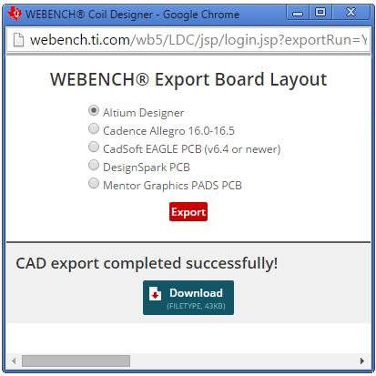 Figure 7 The Export Function Exports
the Coil into PCB Layout Software
Figure 7 The Export Function Exports
the Coil into PCB Layout SoftwareI exported the coil to the Altium Designer format and open the resulting file, as shown in Figure 8.
 Figure 8 The Resulting Sensor Coil When Imported into Altium Designer
The new WEBENCH Coil Designer complements the WEBENCH Inductive Sensing Designer by offering more control over the physical coil properties.
Do you find our WEBENCH tools for inductive sensing useful? Are there other WEBENCH tool features that would make your system design with LDCs easier? If so, leave a note in the comments section below.
Additional Resources
- Read more inductive sensing blogs, including one I wrote about “Five-minute sensor coil design.”
- Watch a WEBENCH Coil Designer video.
- Read this application note for more information on how to design an LDC sensor.
- Check out additional tools in the WEBENCH Design Center.