SLVUCE2 May 2022
3.1.1 Communication without CAN Transceiver
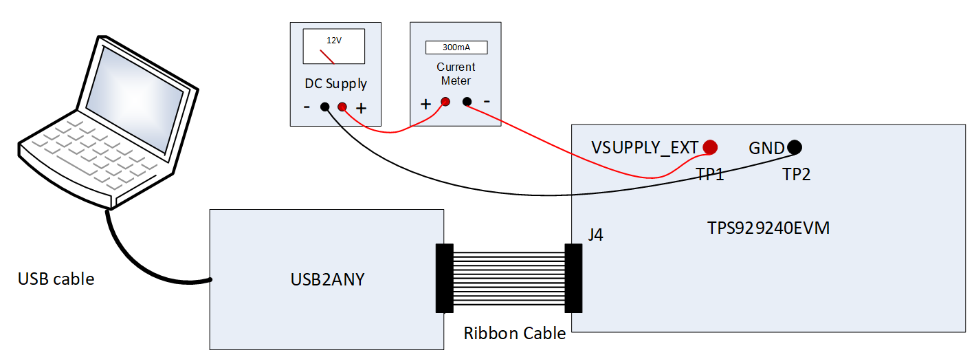
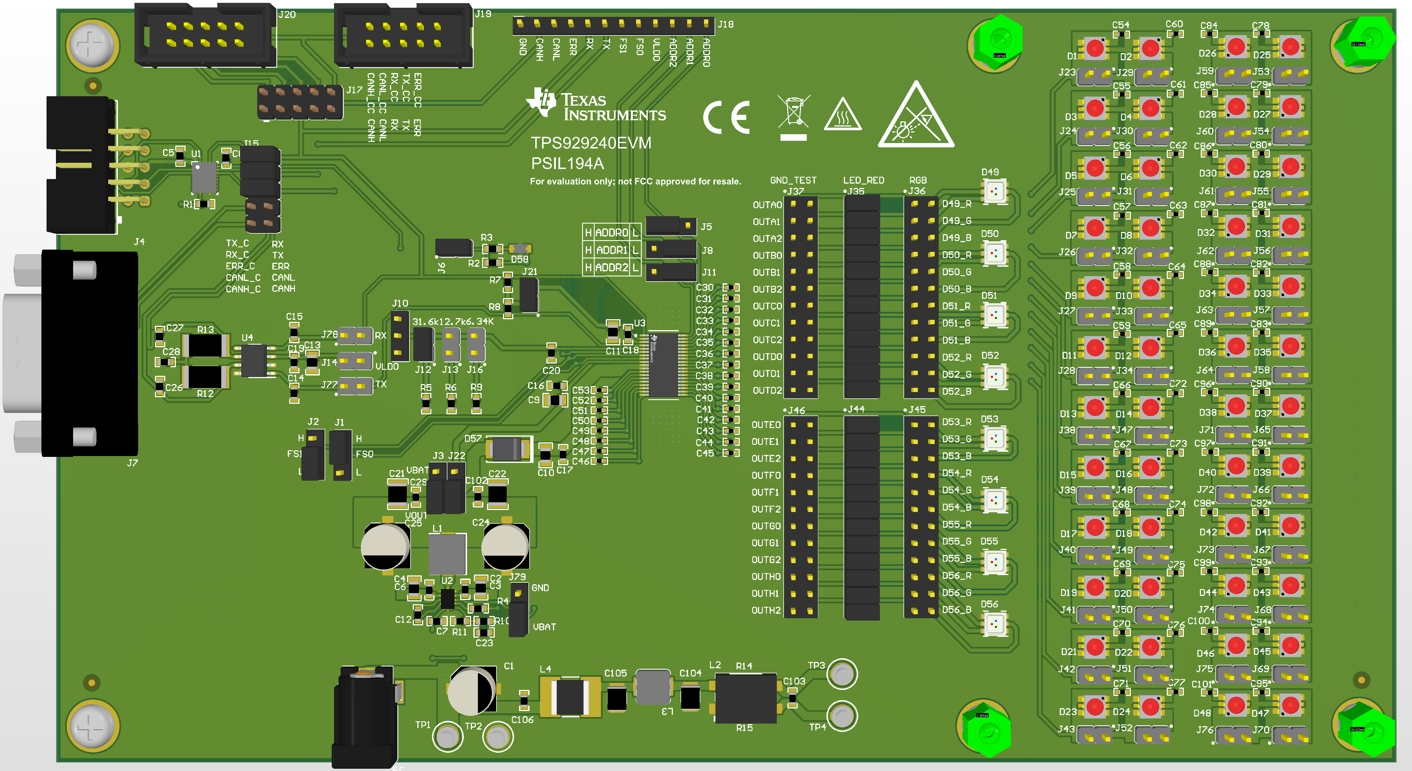
Figure 3-1 shows the hardware setup when TPS929120CANEVM is not used. Figure 3-2 shows the jumper configurations for the TPS929240EVM without TPS929120CANEVM connected. This jumper is the default jumper configuration shipped with the board.
 Figure 3-1 Hardware Setup without CAN
Transceiver
Figure 3-1 Hardware Setup without CAN
Transceiver- Connect a 12-V power supply to TP1 (VSUPPLY_EXT) and TP2 (GND).
- Connect USB2ANY tool to PC through the USB cable.
- Connect USB2ANY tool to the J4 connector of TPS929240EVM through ribbon cable.
 Figure 3-2 TPS929240EVM Jumper Configurations
without TPS929120CANEVM Connected
Figure 3-2 TPS929240EVM Jumper Configurations
without TPS929120CANEVM ConnectedTable 3-1 TPS929240EVM Jumpers Setting
without TPS929240CANEVM Connected
| HEADER | SETTING |
|---|---|
| J6, J12, J21, J35, J44 | Short |
| J17, J10, J13, J16, J36, J37, J45, J46, J78, J77, J14 | Open |
| J15 | Short “TX_C” to “RX”, “RX_C” to “TX”, “ERR_C” to “ERR” |
| J11 | Short “ADDR2” to “L” |
| J8 | Short “ADDR1” to “L” |
| J5 | Short “ADDR0” to “H” |
| J1 | Short “FS0” to “H” |
| J2 | Short “FS1” to “L” |
| J3, J22 | Short to “VOUT” |
| J79 | Short to “VBAT” |
| All headers paralleled with LEDs | Open |