SLOA203 August 2016 DRV10983 , UCC28810
2.1 Optocoupler Circuit to Detect the Firing Angle
In a BLDC motor, the variation of RMS AC source does not change the output DC. The TIDA-00652 reference design (BLDC ceiling fan TI Design) is used to implement TRIAC-based fan control. A small optocoupler-based circuit is connected to the TIDA-00652 BLDC board as shown in Figure 5. The rectified AC is sensed using the optocoupler. As the phase angle of TRIAC is varied, a PWM signal is generated accordingly. The average of PWM is fed to the SPEED pin of the DRV10983 device.
 Figure 5. TRIAC-Based Control of AC Operated BLDC Fan
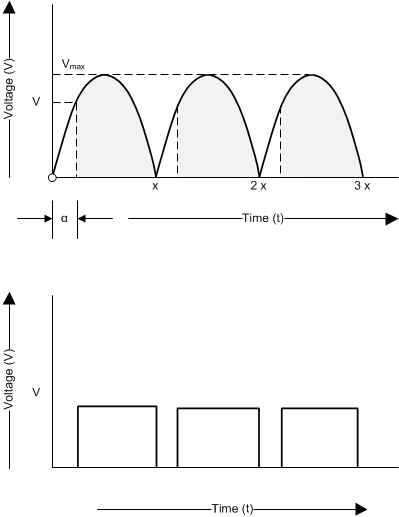
 The AC waveform chopped with a TRIAC at a certain firing angle generates a PWM signal corresponding to the firing angle as shown in Figure 6. This PWM signal is averaged using the RC low-pass filer. The variation in the PWM signal from 10% to 90% results in analog voltage from 0.8 V to 3.3 V correspondingly. The DRV10983 device can be used in Analog control mode and this output analog voltage can be connected to the SPEED pin of the DRV10983 device.
 Figure 6. PWM Signal at Emitter of Optocoupler