SDAA128 November 2025 TCAN2410-Q1 , TCAN2411-Q1 , TCAN2450-Q1 , TCAN2451-Q1 , TCAN2845-Q1 , TCAN2847-Q1 , TCAN2855-Q1 , TCAN2857-Q1
- 1
- Abstract
- Trademarks
- 1 Introduction
- 2 Sleep Mode of the Transceiver vs. Sleep Mode of the SBC
- Wake Up With SPI Communication Active
- 3 Local Wake Up (LWU)
- 4 Digital Wake Up
- 5 Cyclic Wake Up
- 6 Extending the Timer for Cyclic Wake Ups with External Components
- 7 Cyclic Sensing Wake
- 8 CAN BWRR
- 9 Partial Networking
- 10Summary
- 11References
9 Partial Networking
Partial networking is a medium power saving mode for a select group of CAN based SBCs as well as a select group of CAN based transceivers. Partial networking allows for specific transceivers or nodes to be turned on while the rest of the nodes on the CAN bus remain in an off state. Turning on only some of the transceivers/nodes saves total power consumption in the system. There are up to three different partial networking conditions that can be implemented to give the end user precise control of what devices wake up during a selective wake/ Partial Networking application – these are ID verification, DLC verification, and data verification. However, most use cases only use ID verification as that is generally enough control for most systems.
After the device has been configured for partial networking (check the specific device for instructions on how to configure) the device can be put to sleep with Partial Networking enabled. Partial Networking does not begin the verification process until the reception of a WUP – which has the same properties as described in the CAN BWRR section. Upon the reception of the final filtered dominant bit, the device starts the verification process, which dramatically increases the supply current during the detection phase (for example, why it is only a medium power saving mode). The first check is ID verification. Traditionally this is an 11-bit binary string and is used to indicate device priority. During the configuration stage each CAN transceiver device has an ID assigned as well as the option to add an ID mask. The ID verification happens with a combination of the devices own ID as well as the ID mask. The ID mask indicates whether or not a specific ID bit is relevant or if it is a don’t care. For example, assume the device ID is 0b00011000101 and there is an ID mask value of 0b11111111100 – the ones indicate a don’t care value in the ID mask and the zeros represent bits that must be matched. This leaves a final ID check as 0bxxxxxxxxx01 – so for a proper ID match to occur the device requesting the wake up must have an ID with the last 2 bits being 0b01. A proper match can look like 0b11100011101 or 0b10101010101 while an ID value of 0b00011000110 is not matched. If the ID matches and DLC / Data verification isn’t enabled the device then wakes up. The ID can also be extended with a 29-bit address; most modern devices that support partial networking supports classic 11-bit IDs as well as extended 29-bit IDs.
 Figure 9-1 ID and ID Mask Example for
Wake Up Frame (WUF)
Figure 9-1 ID and ID Mask Example for
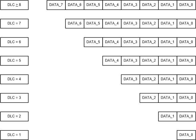
Wake Up Frame (WUF)The next step of verification if Data Length Code (DLC) and data verification are enabled is to check and verify these values. The DLC is the number of bytes being sent in the wake-up message. The DLC code indicates how many bytes are in the wake-up message. This can be anywhere from 0 bytes to 8 bytes. This is checked alongside data verification. Data verification starts by configuring data registers on the device to have a template to match to. For a match to be made there needs to be at least one matched logic one in the same byte and same position within byte.
 Figure 9-2 DLC to Data Byte
 Figure 9-3 Data Validation
Example