ZHCSEG3C September 2015 – July 2016 SN65DP149 , SN75DP149
PRODUCTION DATA.
- 1 特性
- 2 應(yīng)用
- 3 說明
- 4 修訂歷史記錄
- 5 說明 (續(xù))
- 6 Pin Configuration and Functions
-
7 Specifications
- 7.1 Absolute Maximum Ratings
- 7.2 ESD Ratings
- 7.3 Recommended Operating Conditions
- 7.4 Thermal Information
- 7.5 Power Supply Electrical Characteristics
- 7.6 Differential Input Electrical Characteristics
- 7.7 HDMI and DVI TMDS Output Electrical Characteristics
- 7.8 DDC, and I2C Electrical Characteristics
- 7.9 HPD Electrical Characteristics
- 7.10 HDMI and DVI Main Link Switching Characteristics
- 7.11 HPD Switching Characteristics
- 7.12 DDC and I2C Switching Characteristics
- 7.13 Typical Characteristics
- 8 Parameter Measurement Information
- 9 Detailed Description
- 10Application and Implementation
- 11Power Supply Recommendations
- 12Layout
- 13器件和文檔支持
- 14機(jī)械、封裝和可訂購信息
封裝選項(xiàng)
機(jī)械數(shù)據(jù) (封裝 | 引腳)
- RSB|40
散熱焊盤機(jī)械數(shù)據(jù) (封裝 | 引腳)
- RSB|40
訂購信息
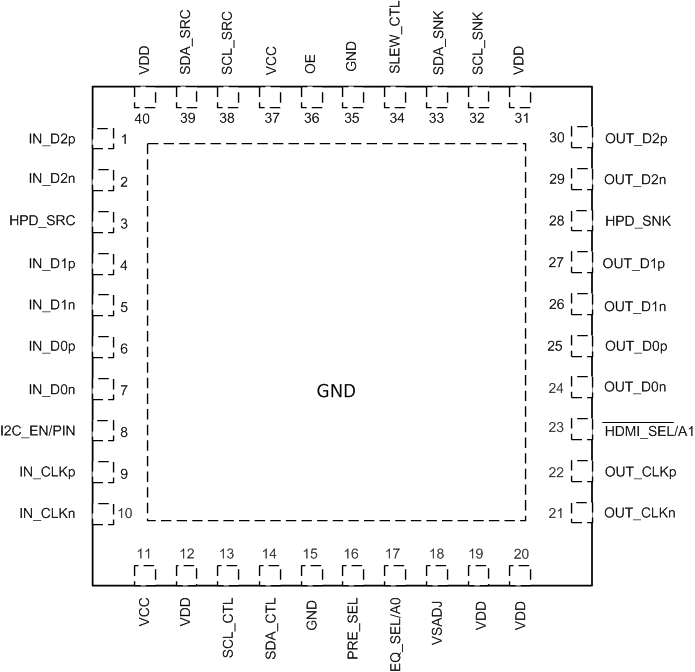
6 Pin Configuration and Functions
RSB Package
40-Pin WQFN
Top View

Pin Functions
| PIN | I/O | DESCRIPTION (1) | |
|---|---|---|---|
| SIGNAL NAME | NO. | ||
| MAIN LINK INPUT PINS (FAIL SAFE) | |||
| IN_D2p IN_D2n |
1 2 |
I | Channel 2 differential input |
| IN_D1p IN_D1n |
4 5 |
I | Channel 1 differential input |
| IN_D0p IN_D0n |
6 7 |
I | Channel 0 differential input |
| IN_CLKp IN_CLKn |
9 10 |
I | Clock differential input |
| MAIN LINK OUTPUT PINS (FAIL SAFE) | |||
| OUT_D2n OUT_D2p |
29 30 |
O | TMDS data 2 differential output |
| OUT_D1n OUT_D1p |
26 27 |
O | TMDS data 1 differential output |
| OUT_D0n OUT_D0p |
24 25 |
O | TMDS data 0 differential output |
| OUT_CLKn OUT_CLKp |
21 22 |
O | TMDS data clock differential output |
| HOT PLUG DETECT PINS | |||
| HPD_SRC | 3 | O | Hot plug detect output |
| HPD_SNK | 28 | I (Failsafe) | Hot plug detect input |
| DDC DATA PINS | |||
| SDA_SRC SCL_SRC |
39 38 |
I/O (Failsafe) | Source side TMDS port bidirectional DDC data line |
| SDA_SNK SCL_SNK |
33 32 |
I/O (Failsafe) | Sink side TMDS port bidirectional DDC data lines |
| CONTROL PINS | |||
| OE | 36 | I | Operation enable/reset pin OE = L: Power-down mode OE = H: Normal operation Internal weak pullup: Resets device when transitions from H to L |
| SLEW_CTL | 34 | I 3 level (1) |
Slew rate control when I2C_EN/PIN = Low. SLEW_CTL = H, fastest data rate (default) SLEW_CTL = L, 5-ps slow SLEW_CTL = No Connect, 10-ps slow When I2C_EN/PIN = High Slew rate is controlled through I2C[4] |
| PRE_SEL | 16 | I 3 level (1) |
PRE_SEL = L: - 2-dB de-emphasis PRE_SEL = No Connect: 0-dB PRE_SEL = H: Reserved Note: (3 level for pin strap programming, but 2 level when I2C[4] address) |
| EQ_SEL/A0 | 17 | I 3 level (1) |
Input Receive Equalization pin strap when I2C_EN/PIN = Low EQ_SEL = L: Fixed EQ at 7.5-dB EQ_SEL = No Connect: Adaptive EQ EQ_SEL = H: Fixed at 14-dB When I2C_EN/PIN = High Address bit 1 Note: (3 level for pin strap programming but 2 level when I2C[4] address) |
| I2C_EN/PIN | 8 | I | I2C_EN/PIN = High; puts device into I2C control mode I2C_EN/PIN = Low; puts device into pin strap mode |
| SCL_CTL | 13 | I | I2C clock signal Note: When I2C_EN/PIN = Low Pin strapping take priority and those functions cannot be changed by I2C |
| SDA_CTL | 14 | I/0 | I2C data signal Note: When I2C_EN/PIN = Low Pin strapping take priority and those functions cannot be changed by I2C |
| Vsadj | 18 | I | TMDS-compliant voltage swing control nominal resistor to GND |
| HDMI_SEL/A1 | 23 | I | HDMI_SEL when I2C_EN/PIN = Low HDMI_SEL = High: Device configured for DVI HDMI_SEL = Low: Device configured for HDMI (Adaptor ID block is readable through I2C When I2C_EN/PIN = High Address bit 2 Note: Weak internal pull down |
| SUPPLY AND GROUND PINS | |||
| VCC | 11, 37 | P | 3.3-V power supply |
| VDD | 12, 19, 20, 31, 40 | P | 1.1-V power supply |
| GND | 15, 35, Thermal Pad | — | Ground |
(1) (H) Logic high (pin strapped to VCC through 65-kΩ resistor); (L) logic low (pin strapped to GND through 65-kΩ resistor); (for mid-level, no connect)